CS 3516: Computer Networking
-
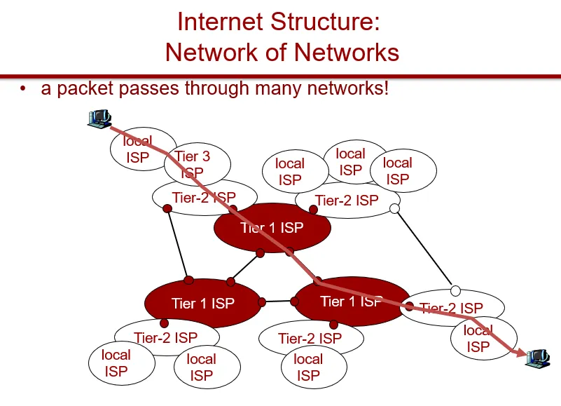
Internet
- An internet: the interconnection of multiple networks into one
- The Internet: the world-wide network that replaced the ARPANET
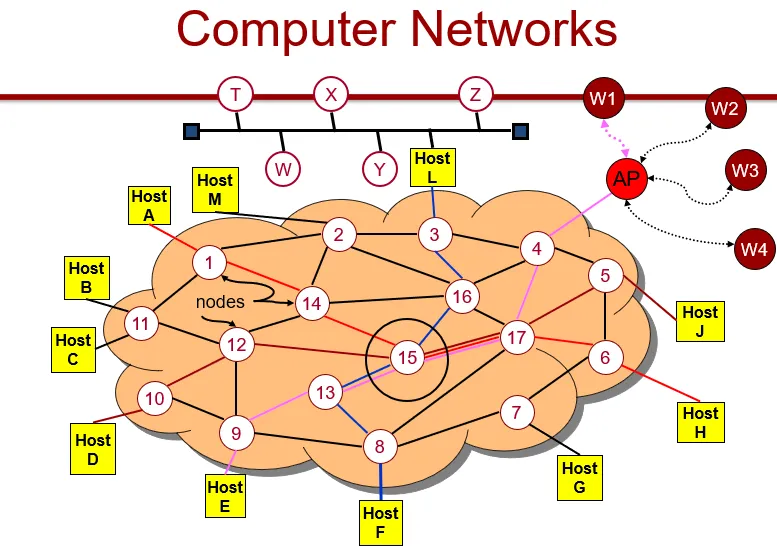
- Hosts or end systems
- Anything that has an address
- Communication links (between ends)
- Packet switches
- Routers (IP address forwarding)
- Link layer switches (ethernet MAC addresses)
- Transmission rate
- Packets
- Routes and paths
- Wifi and sometimes ethernet on PC or laptops
- ISPs
- Protocols
- Examples: TCP, IP
- Format and order of messages and actions taken
- Standards
- Request for comments
- Distributed applications
- APIs for specifying how to transmit
- Example: web browser communicating with web server
-
Living on the network edge
- Devices/types of hosts
- Clients and servers (systems and programs)
- Distributed applications (P2P, can act as client/server)
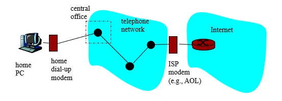
- Access networks
- Telcos
- Central office
- Telephony
-
Transmission technology
- Broadcast
- Logical or a physical concept
- “Broadcast” to subscribed channels
- Multicast
- Communication to a specified group
- This requires a group address (e.g. — multimedia multicast)
- Unicast
- Point-to-point (P2P)
- Specialized version of unicast; there is supposed to be only two entities present
- Broadcast
-
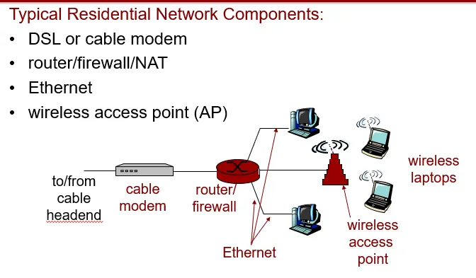
Types of access network
- Dial-up
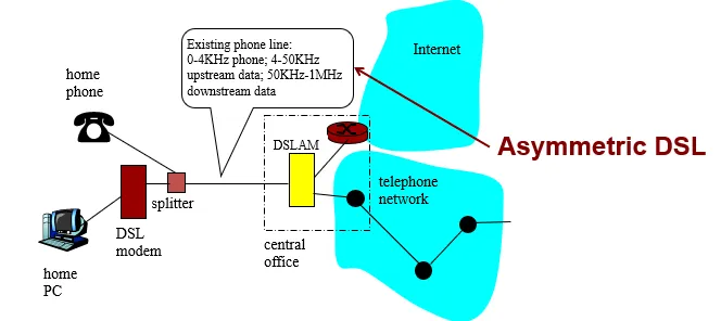
- DSL
- Same market share as Cable in the US
- Outside US, DSL over 90% in many countries
- Twisted pair copper wire
- Asymmetric (upload speed != download speed)
- Very-high speed DSL (VDSL)
- Cable
- Cable head end
- Fiber optic cable between head ends
- 500 to 5,000 homes on a junction (fiber to the neighborhood)
- Hybrid fiber coax (HFC)
- Cable modems
- Shared broadcast medium
- Fiber to the home/premises
- Direct fiber
- Active optical networks
- Passive optical networks
- WiFi
- Wide-Area Wireless Networks
- WiMaX
- LTE
- 5G
-
Transmission medium
- Guided
- DSL, Cable, Fiber
- Unguided
- Wireless: type depends on frequency
- Residential access networks
- Institutional access networks
- Public access networks
- Cellular networks
- Satellite
- Wireless: type depends on frequency
- Twisted-Pair Copper Wire
- Cheap
- Unshielded Twisted Pair (UTP) used within buildings
- Coaxical Cable
- Copper, but concentric (to shield the communication)
- Fiber Optics
- Great for long haul (attenuation, tapping, interference)
- Expensive parts make short-haul costly
- 51.8Mbps to 39.8 Gbps
- Guided
-
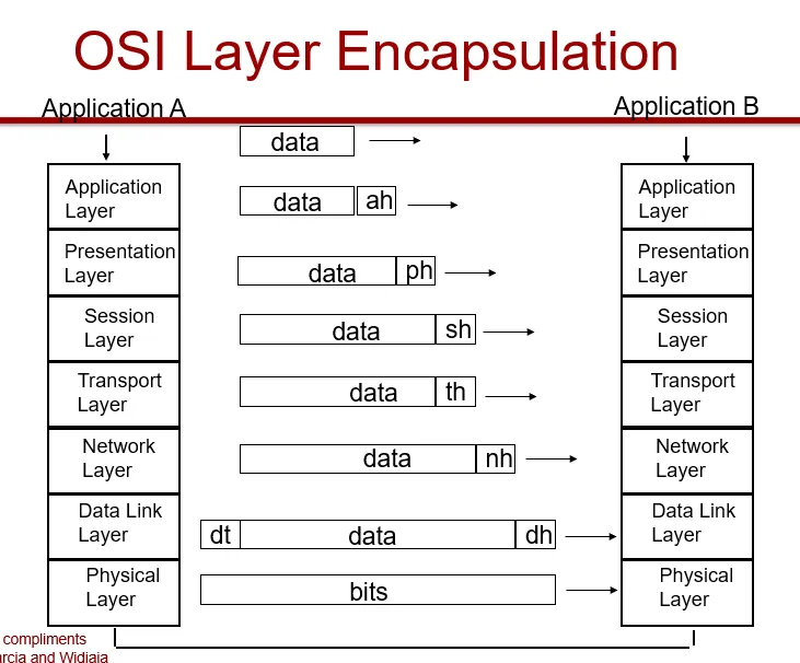
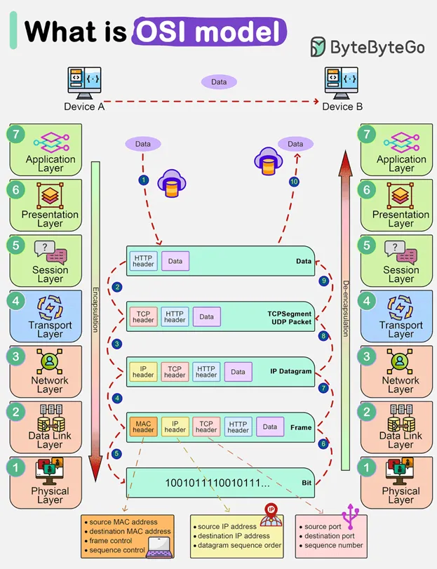
The OSI model
-
Application Layer
- Provides users access to the OSI environment and distributed information services.
-
Presentation Layer
- Provides application processes independence from differences in data representations.
-
Session Layer
- Provides the control structure for communicating between applications.
- Establishes, manages and terminates session connections between cooperating applications.
-
Transport Layer
- Provides reliable transparent transfer of data between end points.
- Provides end-to-end flow control and error recovery.
-
Network Layer
- Provides independence from the data transmission, routing/switching technologies used to connect systems. Responsible for establishing, managing and terminating connections.
-
Data Link Layer
- Provides for reliable transfer of information across the physical layer. Sends and receives frames with the necessary synchronization, flow control and error control.
-
Physical Layer
- Concerned with transmission of unstructured bit stream over a physical medium. Deals with mechanical, electrical, functional and procedural characteristics to access the physical medium.
-
Advantages of layering design
- An explicit structure
- Identification & relationship
- Reference model for discussion
- Abstration for functional locality
- Simplifies the design process
- Modularity of layers
- An explicit structure
-
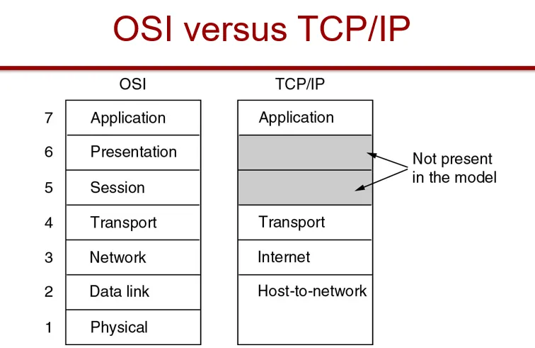
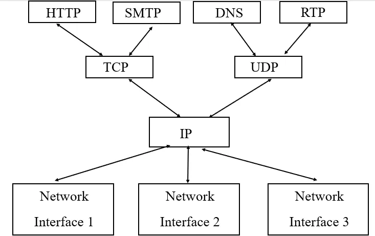
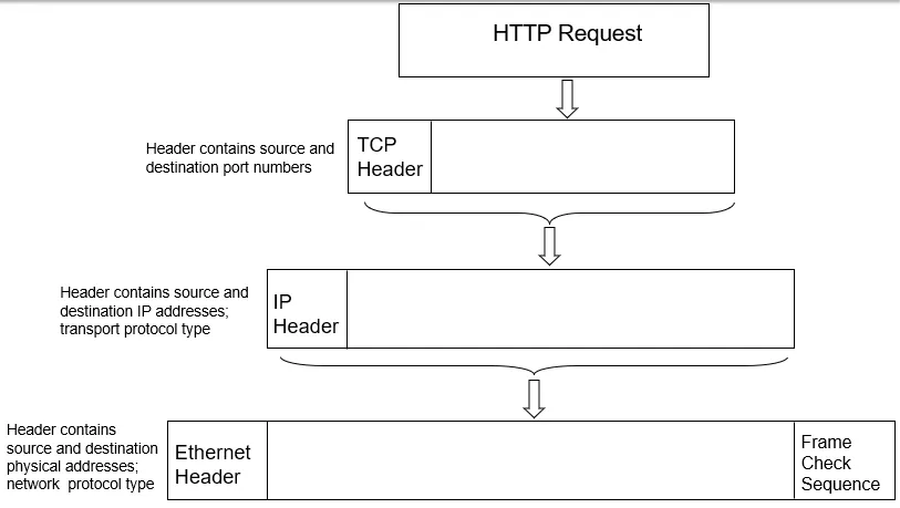
TCP/IP
-
Application: supporting network applications
- Protocols: FTP, SMTP, HTTP
-
Transport: process-process data transfer
- TCP, UDP
-
Network: routing of datagrams from source to destination
- IP, routing protocols
-
Link: data transfer between neighboring network elements
- PPP, Ethernet
- PPP, Ethernet
-
Example
- Client/server relationship
- Server process waits for incoming requests by listening to a port
- Client process makes requests as required
- Server process provides responses to these requests
- The server process usually runs in the background as a daemon (e.g. httpd is the server daemon for HTTP)
- Client/server relationship
-
Currently provides best-effort service
- Packets may be lost
-
General design philosophy
- Keep the core internal operations simple
- Push complications to the hosts/edge
- End hosts: recover lost packets and congestion control
- Operate over any network
-
This design allows IP to scale
-
Only uses IP addresses to identify hosts
- IPv4: 32 bit identifiers
- 1.2.3.4
- Location information embedded in the structure
- Network ID | Host ID → 4 bytes
- IPv6: 128 bit identifiers
- 2001:0db8:85a3:0000:0000:8a2e:0370:7334
- Are used for routing
- Not human-friendly → Use the Domain Name System (DNS) to translate between IP addresses and mnemonic names
- IPv4: 32 bit identifiers
-
TCP (Transmission Control Protocol) vs UDP (User Datagram Protocol)
- TCP
- Connection-oriented: establishes a connection between host and destination before transmission
- Reliability: error detection, re-transmission of lost packets, and flow control to manage data transmission rate
- Ordered delivery
- Heavyweight: slower → data integrity and sequencing → web browsing, email, file transfer
- UDP - Connectionless - Unreliable: up to the application layer to handle errors or lost packets - Low overhead - Small packet loss, low latency → real-time communication: video streaming, VoIP, online gaming, DNS
- TCP
-
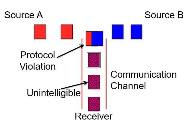
Protocols
- All communication activity in the Internet between machines are governed by protocols
- Definition
- Define format
- Order of messages
- Actions taken upon transmission/receipt
- HTTP (HyperText Transfer Protocol) example - Specifies rules by which the
client and server interact to retrieve a document - Assumes the client and
server can exchange messages directly - The client needs to set up a two-way
connection before the HTTP request
-
Sockets
- Software endpoint that allows processes to send and receive data
- Identified by an IP address and a port number
- Facilitate communication using network protocols
- TCP: stream sockets → reliable, bidirectional, byte-stream communication channel
- UDP: datagram sockets → connectionless, unreliable communication, where each packet is independent
-
Get TCPEchoClient.c + TCPEchoServer.c
-
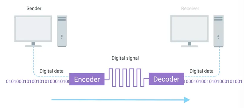
Physical Layer
- Encodes information to send from one party to the next
- Consists of devices and means of transmitting bits across networks
-
1s and 0s are sent over the wires through modulation (varying the voltage of change across the cable)
-
Definitions
- The time to transmit a character ~ encoding method + signaling speed (modulation rate)
- Baud (D) — the number of times/second the signal changes its voltage
- Bandwidth (H) — the range of frequencies that is passed by a channel
- Channel capacity (C) — the data transmission rate over a channel — also data rate ®
- Signals — electric or electromagnetic encoding of data
- Signaling — the propagation of signal along a suitable medium
- Analog signal — a continuously varying electromagnetic wave that may be propagated over a variety of medium depending on the spectrum (e.g., wire, twisted pair, coaxial cable, fiber optic cable, and atmosphere or space propagation)
- Digital signal — a sequence of voltage pulses that may be transmitted over a wire medium
- Note — analog signals — analog data, digital signals — digital data are not the only possibilities
- Modem (mux-demux) — computer hardware device that converts data from a digital format into a format suitable for an analog transmission medium such as telephone or radio
- Codecs (compression-decompression)
- Multiplexing — sharing a resource over time
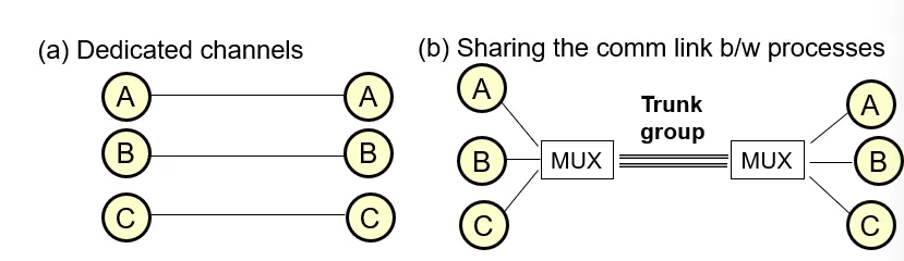
-
Needed when a client and server have multiple processes running
-
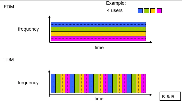
Frequency division multiplexing (FDM) vs. time division multiplexing (TDM) — two techniques for multiplexing
-
FDM
- Available bandwidth divided into multiple non-overlapping frequency bands
- Each data stream assigned a separate frequency band
- Multiple signals transmitted simultaneously over the same medium without interference
- Used in cable TV systems, with different TV channels on different frequency bands
-
TDM
-
Available time divided into multiple time slots
-
Each data stream assigned a specific time slot for transmission
-
Multiple data streams share the same transmission medium by taking turns
-
Used in digital communication systems like Time Division Multiple Access (TDMA) in cellular networks
-
-
-
Encoding bits on a wire
-
Signals propagate over physical medium
- Modulating electromagnetic waves (vary voltage)
-
-
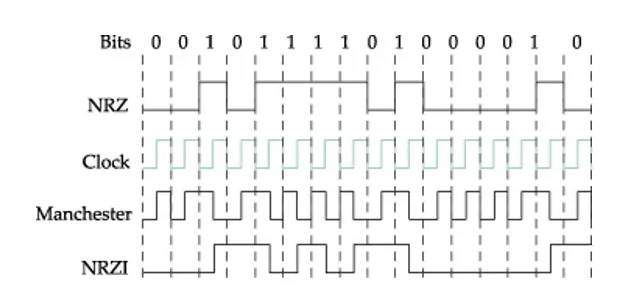
Non-Return to Zero (NRZ) encoding
-
0 = low; 1 = high
-
Problem: May have sequence of consecutive zeroes or ones
-
Baseline wander
-
Receiver averages line voltage to estimate high vs. low signal
-
Consecutive 0s/1s pushes the average around
-
-
Clock recovery broken
-
Sender/receiver clocks must be synchronized
-
High/low bits help make resynching possible
-
-
-
-
NRZ Inverted (NRZI)
-
Stay at current signal to send a 0
-
Transition to send a 1
-
Helps with consecutive 1s
-
Doesn’t help with consecutive 0s
-
-
Manchester Encoding
-
Merges clock with exclusive-OR of the data being transmitted using NRZ
-
Clock goes from low to high once each clock cycle
-
Low to high = 0, High to low = 1
-
x2 the transition rate on the link = ½ time for receiver to detect signal pulse → 50% efficiency
-
-
4B/5B Encoding
-
Translation table from original bits into bit pattern with some variation in the bits
-
Examples:
-
0000 → 11110 1111 → 11101
-
No more than 1 leading 0, no more than 2 trailing 0s. Therefore, no more than 3 0’s in a row.
-
Sent using NRZI
-
80% efficiency
-
Physical Media: guided (solid media: copper, coax, fiber) and unguided (radio)
-
Coaxial cable
-
Two concentric copper conductors
-
Bidirectional
-
Baseband
-
Single channel on cable
-
High speed without modulation
-
Legacy Ethernet
-
-
Broadband
- Multiple channels on cable
-
-
Twisted pair
-
Pairs of copper wires that are twisted together
-
Act as a single conduit for information
-
Protect against electromagnetic interference & cross-talk
-
-
Most common type used for connecting computing devices
-
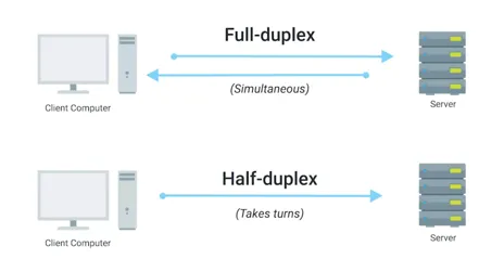
Duplex vs. simplex (unidirectional) communication
-
-
-
Fiber optic
-
Glass fiber carrying light pulses, each pulse a bit
-
High-speed operation
- P2P transmission (10’s-100’s Gps)
-
Low error rate: repeaters spaced far apart; immune to electromagnetic noise
-
-
Radio signals
-
Signal carried in electromagnetic spectrum
-
No physical “wire”
-
Bidirectional
-
Propagation environment effects:
-
Reflection
-
Obstruction by objects
-
Interference
-
-
-
End system choices
- Dial-up modem
-
Uses existing telephony infrastructure
-
Digital Subscriber LIne (ADSL)
-
Uses existing telephony infrastructure
-
Cable modems — residential access
-
Modem — modulator and demodulator
-
Uses cable TV infrastructure
-
HFC: hybrid fiber coax
- Asymmetric
-
Network of cable and fiber attaches homes to ISP router
-
Homes share access to router
-
Unlike DSL, which has dedicated access
-
-
-
Fiber to the home
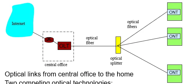
-
Two competing optical technologies
-
Passive Opticla network (PON)
-
Active Optical Network (AON)
-
-
Higher Internet rates, also carries TV and phone services
-
Ethernet Internet access
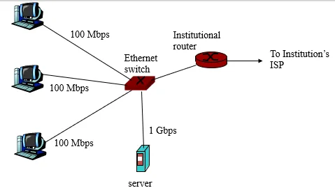
-
Typically used in companies, universities, etc
-
Today, end systems typically connect into Ethernet switch
-
Wireless Access Networks
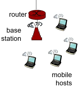
- Residential Networks
-
Data Link Layer
-
Framing
-
Breaking bits into manageable units called frame
-
Implemented by network adaptor
-
Main approaches
-
Sentinel-based
-
Delineate frames with a special pattern (e.g., 01111110)
-
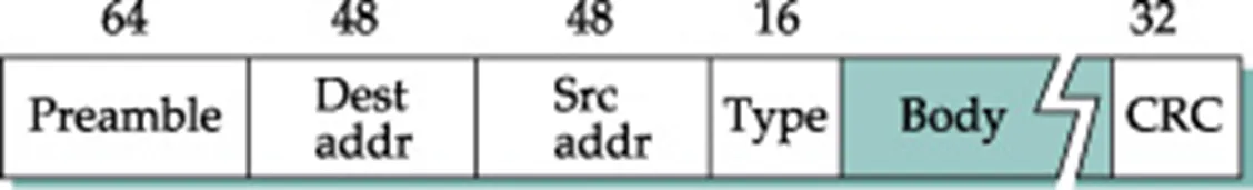
Ethernet
-
-
-
-
-
Problem: special pattern is in the payload
-
Solution: Bit stuffing
-
Sender: insert 0 after 5 consecutive 1s
-
Receiver: delete 0 that follows 5 consecutive 1s
-
Commonly used in the Ethernet
-
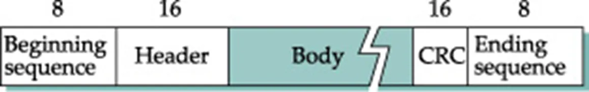
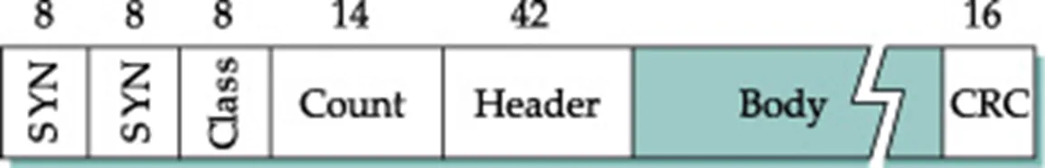
Counter-based
-
Include a payload length field in the header
-
Problem: count field corrupted
-
Solution: corruption caught by CRC calculation
-
-
This example is from a protocol called Digital Data Communication Message (DDCM)
-
Commonly used in TCP and IP header
-
Clock-based
-
Medium Access
-
Ethernet (bus)
-
CSMA/CD
-
Carrier Sense: able to listen to see if anyone else is transmitting at the same time
-
Multiple Access: multiple people are trying to communicate over the bus simultaneously. Guarantees that they can transmit simultaneously and help with error recovery
-
Collision Detection
-
-
Frame format
-
-
-
Addresses
-
unique, 48 bit addresses assigned to each NIC
-
Example: 08:00:E4:B1:02
-
Broadcast: all 1s
-
Multicast: first bit is 1
-
-
Bandwidth: 10Mbps, 100Mbps, 1Gbps
-
Length: 2500m (500m segments with 4 repeaters)
-
Problem: fair distributed resource management
-
Transmit algorithm
-
If line is idle
-
Send immediately
-
Upper bound of 1500 bytes
-
Must wait 9.6 microsecs between frames
-
-
If line is busy
- Wait until idle, transmit immediately
-
-
Collisions
-
If there is a collision…
-
Send JAM for 32 bits, then stop transmitting
-
Minimum frame: 64 bytes (header, plus 46 data)
-
Delay and try again:
-
1st time: 0 or 51.2 microseconds
-
2nd time: 0, 51.2, or 102.4 microseconds
-
nth time: k * 51.2 microsecs, random k = 0…2n-1
-
Give up after a lot of tries (usually 16)
-
Exponential back-off
- Doubling the amount of wait time
-
-
-
Ethernet: lousy at fairness and collisions
-
Still in use because
-
Cheap
-
Easy to administer
-
Multiple access is actually less common
-
Ethernet hub (repeater with >2 ports)/repeater are not popular anymore
-
Ethernet switches are more popular
-
-
-
-
Ethernet networks
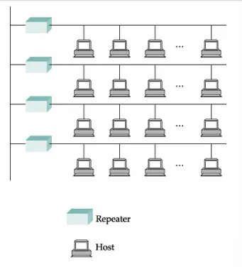
-
Bus topology, multiple hosts connected to each other
-
Repeater devices attach segments together
-
“Hubs” commonly used for this
-
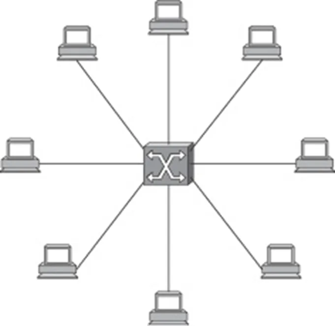
Hubs enabled branching networks and star topologies with direct host connections.
-
Twisted-pair cables replaced thick coax, connecting hosts directly to hubs.
-
Switches forwarded packets based on destination addresses, unlike hubs operating at the bit layer.
-
Despite interchangeability, switches gradually replaced hubs in wiring closets for better performance.
-
-
-
Is this what is used in Ethernet networks today?
- NO. Switch-based topologies using these old hubs
-
Wireless (802.11)
-
Can use radio or infrared
- Infrared diffused, but only about 10m
-
11Mbps, 54Mbps
- With 5G (current), you are transmitting faster than that
-
Avoiding interference (Spread Spectrum)
-
Frequency hopping
-
Direct sequence (chipping code)
-
-
Ad-hoc Wireless
-
Multiple Access Collision Avoidance (MACA)
-
Request to Send (RTS)
-
Recipient sends Clear to Send (CTS)
-
-
What do you do if
-
You see a CTS and RTS, someone is communicating with you so you should listen
-
you see a CTS, but you’re not the sender?
-
you see an RTS, but no corresponding CTS?
-
The other party is not authorized to send
-
Or you are not able to hear other party replying (out-of-range)
-
-
-
Other features
-
ACK signal
-
Mangled RTS messages?
-
-
-
Wireless with Access Points
-
Handshaking process:
-
Mobile device sends Probe
-
Base station replies with Probe Response
-
Mobile device sends Association Request
-
Base station sends Association Response
-
-
Active scanning
- During an active scan, the client radio transmits a probe request and listens for a probe response from an AP.
-
Beacons
- short, regular transmissions from access points that inform user devices about available Wi-Fi services and nearby access points.
-
-
-
Token Ring (FDDI)
-
Ring of computers
-
Data travels either clockwise or anti-clockwise, but not both
- Not a series of point links
-
Token allows possessor to spring
-
Send data collected by speaker
-
Round-robin, limited quantum
-
-
Node failure breaks the ring?
- Electromechanical Relay can fix it
-
Multi-station access unit (MSAU)
- Dynamic relays, makes it look like a star topology
-
Access control?
-
Token: 24 bits
-
Seize the token, send preamble
-
Token Holding Time: 10ms
-
Reservation bits in frame header
-
Early release vs. delayed release
-
-
Confirmed delivery (A bit, C bit)
-
Monitors
-
Distributed Election
- Candidates run (claim token), highest address wins
-
Monitor must:
-
Add delay when needed
-
Ensuring a token exists
-
Timer used to notice missing token
-
Reaping checksum errors and orphans
-
Monitor bit
-
Detecting subtle breaks with beacons
-
-
-
FDDI (optic fiber) vs. Token Ring
-
Changes due to fiber instead of copper
-
Relays not the same
-
Dual ring structure
-
4B/5B encoding vs. differential Manchester
-
Uses control signals instead of illegal encoding
-
-
-
Packet switching
-
-
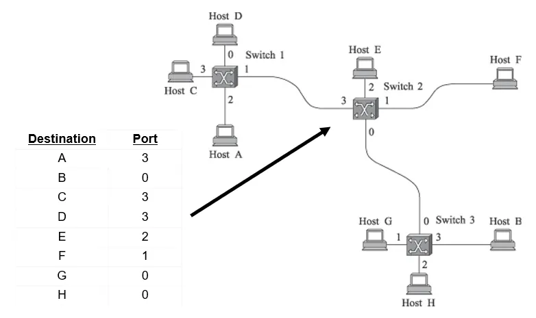
Switching and Forwarding
-
Large networks can be constructed with switches
-
Can connect hosts/switches via point-to-point links
-
Adding hosts to a switch may not decrease performance for other hosts
-
Datagrams
-
-
Connectionless / Immediate service
-
Think of looking at one envelope at a time and forwarding it to its destination
-
Host never knows if the network can handle the traffic
-
Packets traverse independently
-
Even if they are part of the same message
-
Failures may not bring the network down
-
Source Routing
-
Source provides full switching information in header of packet
-
Header size?
- Become very large
-
Large networks?
- Not great for large n/ws
-
Implementation and Performance
-
Commodity machines with several network cards
-
Direct memory access, CPU header inspection
-
I/O and memory bandwidth limiting component
- Packets copied twice
-
Small packets require more header lookups
-
Specially designed switches avoid this contention with hardware
-
-
-
Spanning Tree
-
Switch Design
-
Input/Output Ports, Switching Fabric (n/w topology)
- Fabric has big impact on the performance
-
Fabric very simple: takes packet from input port to output port
- Self-routing fabrics do the heavy lifting themselves
-
FIFO queue can lead to head-of-line blocking
-
Traffic bottlenecks like in Worcester
-
Pure output buffering
-
-
Switching fabric
-
Shared Bus
-
Shared Memory
- High speed memory, avoids I/O bus
-
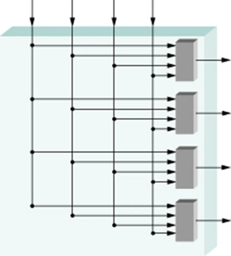
Crossbar
-
-
-
Every input has direct channel to every output
-
Self-routing
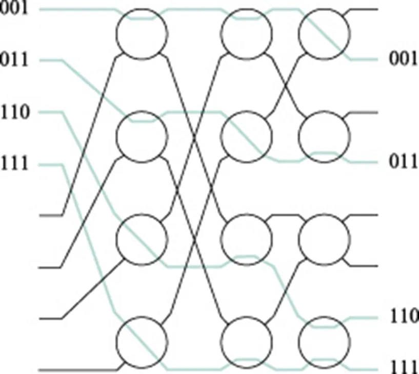
-
Hierarchy of cross-bar switches
-
Circuit-switching and message switching are now obsolete.
-
Store-and- forward, datagram packet switching (IP routers) dominates the Internet.
-
Cell switching and virtual circuits (ATM switches) still exists in ATM networks.
-
The external protocol abstraction to the subnet may differ from the internal subnet view.
- e.g. TCP is connection-oriented protocol that runs on top of a datagram IP protocol
-
MAC Addresses — layer 2 address
-
48-bit address that is burned on the network interface (NIC)
-
Physical address of the device, also known as the real address
-
Example: 00:CC:34:D3:B4:23
- Represented as 6 groups of 2 hexadecimal digits, separated by colons
-
When converted to binary, every hex character is represented by four bits, resulting in a 48-bit address
-
The first three groups are known as OUI — Organization Unique Identifier
- Identifies the manufacturer of the network equipment
-
Broadcast MAC address: all F’s FF:FF:FF:FF:FF:FF (reaches all hosts on the same network)
-
-
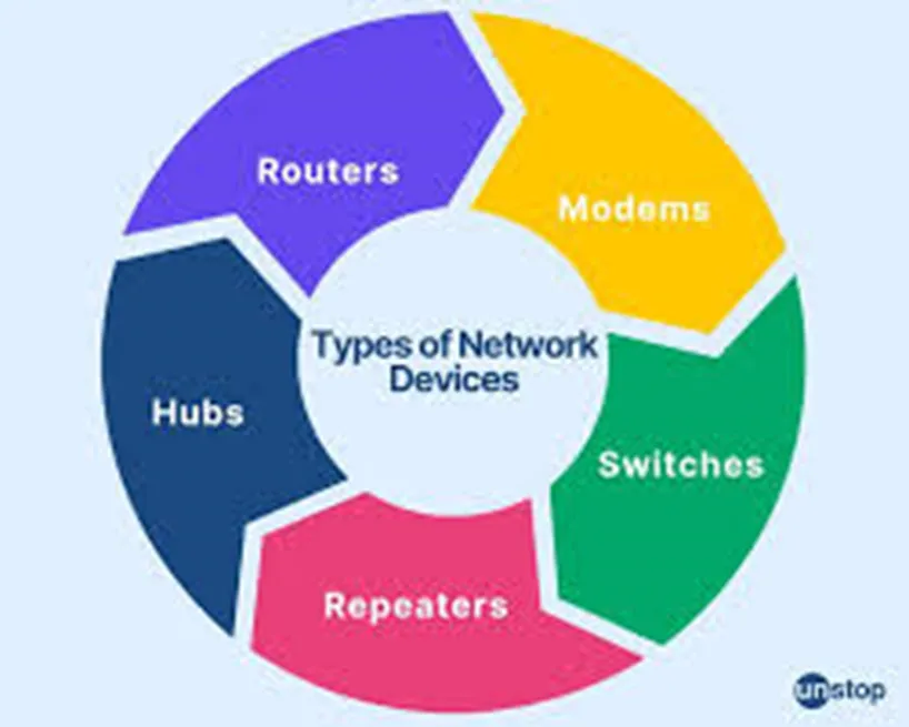
Network devices
-
Repeaters
-
Layer 1 device
-
Repeat signals, receives a signal and retransmit it
-
-
Hubs
-
Layer 1 device
-
Operates in half-duplex mode — send/receive data at any time
-
Has multiple input and output ports allowing multiple devices to connect
-
Data received on one port is forwarded out all other ports (single broadcast domain)
-
Cannot learn MAC addresses
-
Not great with security because everyone receives a copy of the data
-
-
Bridge
-
Layer 2 device
-
Learns MAC addresses
-
Uses a Content Addressable Memory (CAM) table to store port and MAC address information
-
Frame forwarding is software-based
-
-
Switch
-
Layer 2 device
-
Learns MAC addresses
-
Single broadcast domain — every connected device gets broadcast messages. Every port on a switch is the same LAN
-
Specialized chips are used for frame forwarding, resulting in better performance
-
Supports VLANs
-
-
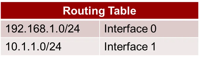
Router
-
Layer 3 device
-
Routes packets between different networks
-
Uses routing tables to make routing decisions
-
On a router, each port is its own broadcast domain
-
-
Broadcast and Multicast
-
Broadcast is pretty simple
- Send to all but sender
-
Multicast could be (and is) done the same way
-
Better trick would be to use learning bridge method
-
A learning bridge listens to all frames in two LAN segments and learns the location of each physical address. It also operates similarly to layer 2 switches, learning which computers are on each side of the bridge.
-
-
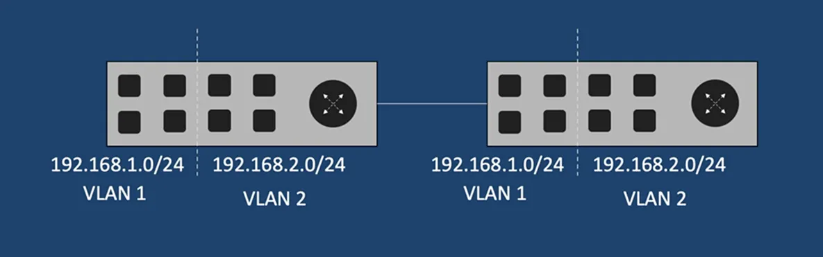
Solution: Virtual LAN (VLAN)
-
Solution to the problem with broadcasting
-
A technique that lets you have multiple logical LANs operating on the same physical equipment
-
-
-
Example: you can isolate security cameras in your organization by putting them on a VLAN protected by a firewall so not intruder can port scan and get access to this isolated VLAN
-
By default, VLANs do not talk to each other
- Layer 3 device is needed for the communication
-
Different policies can be applied to traffic coming from different VLANs
-
Say, prioritizing voice traffic over data
-
Prioritizing data for customers paying more $$ vs those who have cheaper internet packages
-
-
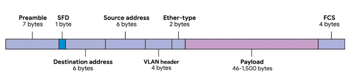
Dissecting an Ethernet frame
-
An Ethernet Frame is a highly structured collection of information presented in a specific order.
-
network interfaces at the physical layer can convert a stream of bits traveling across a link into meaningful data or vice versa.
-
Almost all sections of an Ethernet frame are mandatory, and most of them have a fixed size.
-
Keeping in mind, each MAC address is 48 bits
-
-
Preamble
-
The t in an Ethernet frame is a 64-bit sequence of 1s and 0s that allows the receiver to synchronize with the signal. It is the first 8 bytes of an Ethernet frame. The preamble is a “digital handshake” that ensures the recipient is on the same page about what will be sent. Without a preamble, the recipient would not understand the data, leading to failure.
- informs the receiving system that a frame is starting and enables synchronization.
-
SFD (Start Frame Delimiter) — signifies that the Destination MAC Address field begins with the next byte
-
-
Payload
-
In networking terms, is the actual data being transported, which is everything that isn’t a header (46 — 1500 bytes)
-
Contains all of the data from higher layer
-
-
Frame check sequence
-
A 4-byte (32 bit) number that represents a checksum value for the entire frame
-
CRC: an important concept for data integrity and is used all over computing, not just network transmission.
-
A CRC is basically a mathematical transformation that uses polynomial division to create a number that represents a larger set of data. Anytime you perform a CRC against a set of data, you should end up with the same checksum number.
-
-
Collision domain
-
A collision domain refers to how many devices can send data at the same time.
-
When packets collide => data loss
-
On a hub, if more than one device sends data, then collision will occur. Hub is a single collision domain
-
On a switch, number of collision domains = number of ports
-
On a router, number of collision domain = number of ports (same as a switch)
-
-
Bridges and LAN switches
-
Promiscuous forwarding
-
Learning bridges
-
Empty table?
-
TTLs for entries
-
-
If there is no direct final address, flood every other port but the port the data came from
-
Flooding is bad → form loops
-
LAN Loops
- Spanning Tree Algorithm
-
-
Spanning Tree Algorithm
-
Loops must be broken
-
Smallest ID = root
-
Shortest path to root wins
-
Ties broken by node ID
-
Messages
-
ID of sender
-
ID of the root
-
Distance from sender to root
-
-
Limitations of Bridges
-
Spanning tree algorithm scales linearly
-
Broadcasts don’t scale
-
Virtual LANs
-
Artificial associations between switch ports
-
Requires additional header (and pruning)
-
-
Bridges can only connect networks with similar addressing schemes
-
Bridges introduce delay, loss, and reordering can happen
-
-
Error Detection
-
Detect and correct errors when possible
-
CRC (cyclic redundancy check) commonly used
-
Strong protection against errors
-
Uses finite fields branch of mathematics
-
Simpler approaches
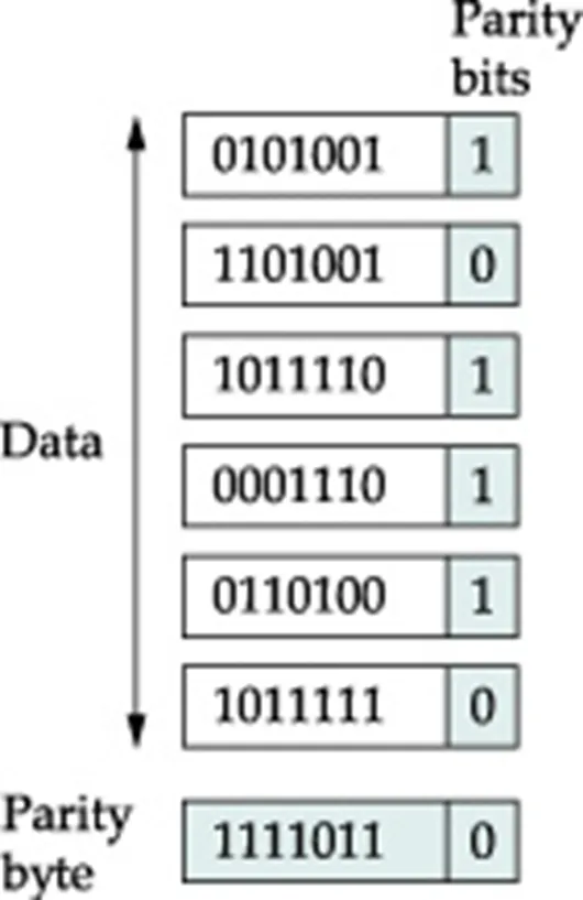
- 2D parity
-
-
Even parity bits to 7 bit codes
-
Extra byte (row) at end of frame to do parity across columns
-
Checksums
-
Not link layer, but relevant anyway
-
One’s complement arithmetic
-
Not so great against errors
- Example: an error that increments by 2 can be missed if a later error decrements by 2
-
Benefits:
-
Small number of redundant bits
-
Easy to implement in software
-
Last line of defense: adequate?
-
-
-
Basically adding redundant information to packets to make error detection possible
-
These bits are “error-detecting codes”
-
Performance Metrics
- How do Loss and Delay occur?
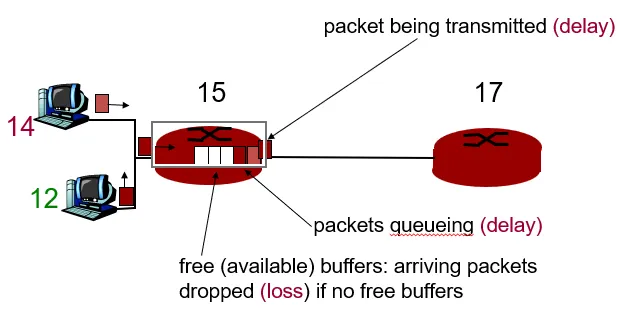
-
Packets queue in router buffers
- Sum of the arriving packets at the router > the output link capacity
-
Generic Performance Metrics
-
Utilization
- the percentage of time a device is busy servicing a “customer”.
-
Throughput
- the number of jobs processed by the “system” per unit time.
-
Response time
- the time required to receive a response to a request (round-trip time (RTT) ).
-
Delay
- the time to traverse from one end to the other of a system.
-
-
Network performance measures
-
Channel utilization:: the average fraction of time a channel is busy [e.g. Util = 0.8]
- when overhead is taken into account (i.e., it is excluded from the useful bits sent), channel utilization is often referred to as channel efficiency.
-
Throughput:: bits/sec. successfully sent
-
[e.g. Tput = 10 Mbps]
-
throughput:: rate (bits/time unit) at which bits transferred between sender/receiver
-
instantaneous: rate at given point in time
-
average: rate over longer period of time
-
-
-
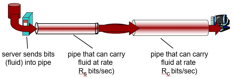
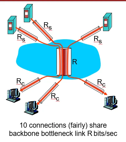
Bottleneck: link on end-end path that constrains end-end throughput
-
Throughput: Internet scenario
-
Per-connection e2e throughput = min(Rc, Rs, R/10)
-
In practice, Rc or Rs is often the bottleneck
-
The last mile link has capacity Rc
-
-
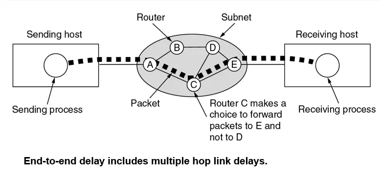
End-to-End Packet Delay — time to delivery of a packet from source to destination = sum of the delays on each subnet link traversed by the packet
-
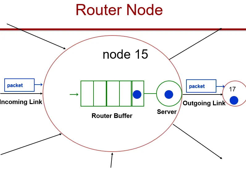
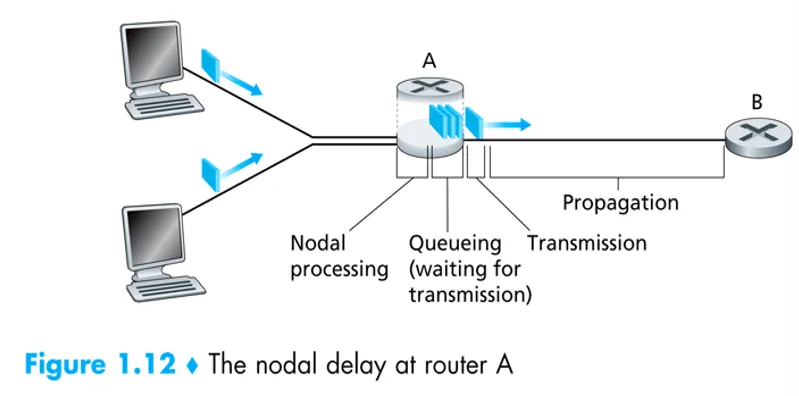
Processing at node
-
Checking for bit errors
-
Determine output link
-
Moving packet from input queue to output queue
- Table lookup time (see routing algorithms)
-
-
Queuing delay
-
time waiting at output link for transmission
-
depends on congestion level of router
-
-
Transmission delay
-
R=link bandwidth (bps)
-
L=packet length (bits)
-
time to send bits into link = L/R
-
-
Propagation delay
-
d = length of physical link
-
s = propagation speed in medium (~2x10⁸ m/sec)
-
propagation delay = d/s
-
-
The Network Layer
- Internet Protocol — IP
-
The Internet was Once Classy…
-
Ethernet addresses globally unique, but flat
-
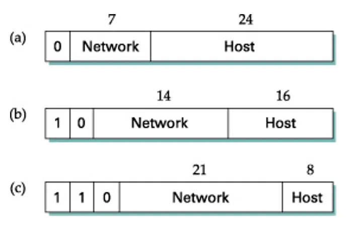
IP addresses are hierarchical
-
Network identifier portion, host identifier portion
-
Addresses are 32 bits
-
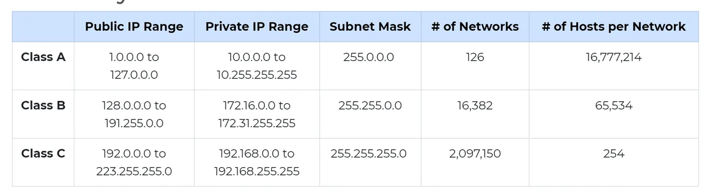
Divided into “classes” based on number of associated hosts
-
Most common:
-
-
Class Schemes
-
The Internet is now Classless
-
Classless Interdomain Routing (CIDR)
-
Class-based routing is not all that efficient
-
Class A address range can’t be subdivided
-
Everything happens on an 8-bit boundary
-
Wastes usable address space
-
-
CIDR allows you to specify the length of the network part:
-
1.2.0.0/16 = 16 bits are network, 16 for hosts
- Same division as a Class B network
-
Need not divide on byte boundary
-
-
-
Subnet mask
-
A 32-bit number
-
Divide an IP address into a host portion and network portion.
-
Defines the range of hosts available within the network.
-
The IP address network portion identifies the network on which a host resides.
-
The IP address host portion identifies the host within the network. Together, the host and network portion make up the host’s unique IP address.
-
-
Subnet example
-
Two hosts:
-
1.2.3.4
0000 0001 0000 0010 0000 0011 0000 0100 -
1.2.3.150
0000 0001 0000 0010 0000 0011 1001 0110
-
-
Subnet Mask: 255.255.255.0
1111 1111 1111 1111 1111 1111 0000 0000 -
Are they in the same network?
-
Binary AND operation between each host and the subnet
-
Same result for both hosts?
-
-
Here, /24 and subnet mask 255:255:255:0 are equivalent: first 24 bits for network group identification, last 8 bits for host identification
-
-
CIDR vs. Subnetting
-
CIDR lets routers determine which network is associated with a set of hosts
-
Hosts within a network have to figure out if they are in the same network or not
-
Can bypass a router if they are
-
They use subnets to figure it out
-
-
How does subnetting work?
- Given a subnet mask and perform a binary AND
-
-
Fragmentation and Reassembly
-
Maximum Transmission Unit (MTU)
-
Recall that an ethernet packet had a limit of 1500 bytes
-
Routers can split packets into pieces for hosts to reassemble
-
Breaking up of info into smaller chunks at the end system is called segmentation. And the same thing when performed at the router is called fragmentation (a lot of work for routers)
-
Routers do not reassemble => end hosts would need to
-
-
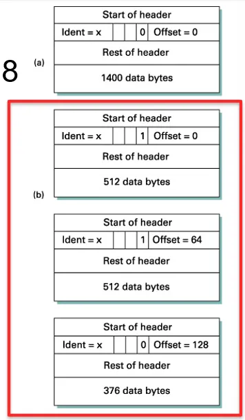
Identifier, Flags (MF), Offset (/8) fields involved
-
Identifier — original packet being sliced and diced
-
MF (more fragments field) — more fragments for this packet coming along
-
Offset — which fragment within that packet is being dealt with
-
-
-
Fragmentation Example
-
MTU = 512 bytes
-
Offsets must be divisible by 8
-
Prefix lookup in routers
-
Efficient lookups for forwarding packets
-
Hash tables
-
A table for prefix length 8, one for 9, one for 10,…
-
Look them up in parallel (easy in hardware)
-
-
Tries
-
-
-
Class-based Lookups
-
Exact matches, no longest prefix
-
Different hash table for each of 3 lengths
-
-
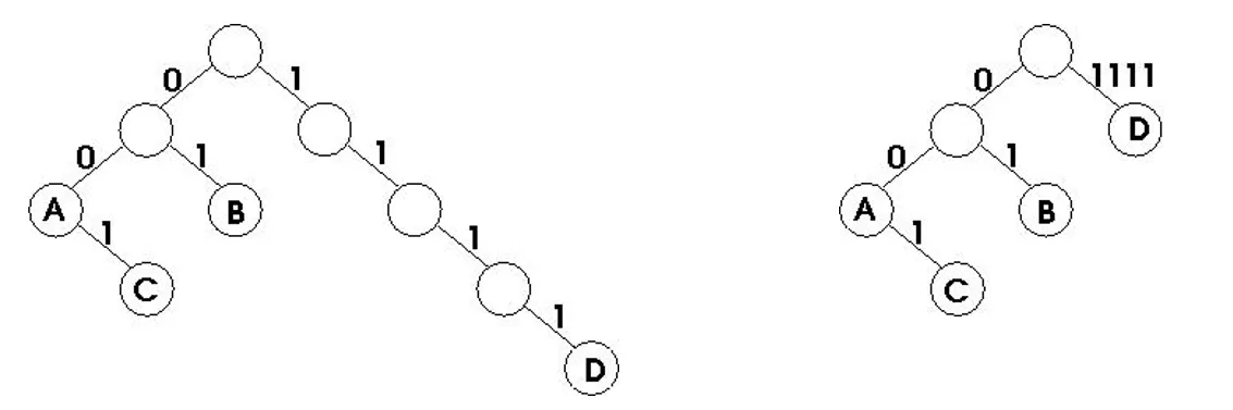
Longest Prefix Matching (CIDR prefixes can vary)
-
Converts IP address into binary
-
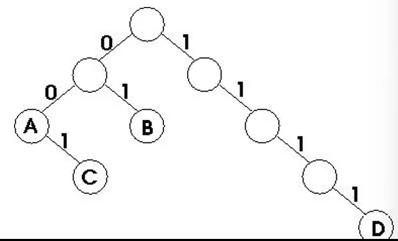
Use Trie data structure
- Tree-based DS with bits encoded on the edges of the trie
-
-
Each node traversal, a bit consumed
-
Each node can store network information
- Store before looking up next bit
-
Abort on null child branch
-
Example
-
A: 00*, B: 01*,
-
C: 001*, D: 1111*
-
-
Path compressed trie
-
Same idea, but you can store multiple identical bits on the same link
-
What benefit could this scheme have?
-
-
Multi-bit Tries
-
Each step consumes multiple bits (“stride”)
-
Why does this help?
-
What if the prefix is odd length and your stride is even?
-
Treat as special cases and allow odd number
-
Expand they trie to fill out two even values of it
-
-
-
Prefix Expansion
-
Shorter prefixes can be rewritten as multiple longer prefixes
-
001* can also be
-
0010* and 0011*
-
00100*, 00101*, 00110*, 00111*
-
-
Why would we want to do this?
-
Always add a bit to expand the tree -> avoid the need for extra special cases
-
Multi-bit trie — this allows you to have a trie of size 2
-
-
-
Parallel hash tables
-
For each prefix length, 1…32, create hash table
-
Add prefix in appropriate table
-
When doing a lookup, create hashes and do lookups under each table for best match
-
-
Prefix expansion may let us get by with fewer tables
-
-
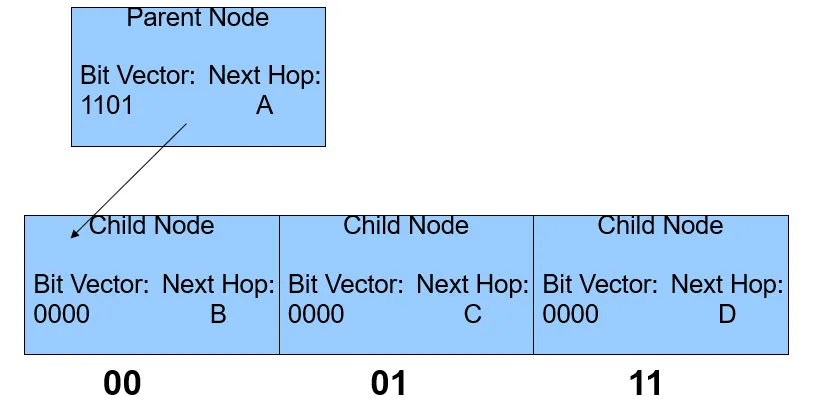
What’s used in modern routers?
-
A fancy multi-bit trie (Tree Bitmaps)
-
Uses a bit vector to indicate present children and adjacent memory allocation
-
1101 -> I have three children — one is missing. The one that is missing has a pattern 10. So three children are 00, 01, 10 (missing), so third child is 11
-
-
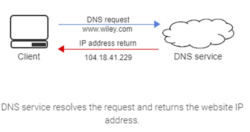
DNS
-
Translate names to IP address
- Also IP address to names
-
Distributed system
- Each domain manages its own DNS records
-
-
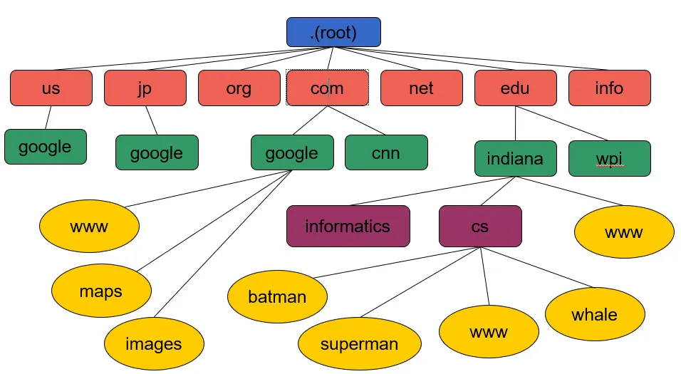
Domain Namespace
-
The organized hierarchy of DNS administrative domains throughout the world
-
A DNS zone is a distinct domain namespace part that is delegated to a legal entity.
- Ex: A person, organization, or company.
-
-
Why do we need DNS?
-
Routing is done on IP addresses
-
Great for computers → longest prefix match
-
Bad for people, not easy to remember
-
-
People like names
- Not so great for computers
-
-
Why a distributed system?
-
Historically names managed by hosts.txt file
-
File was sent to every host online
-
Large and difficult to manage
-
Lack of hierarchical structure leads to name collisions
-
-
Centralized systems have single point of failure
-
-
URL Structure
-
DNS defines a domain namespace, which specifies
-
top-level domains (TLD)
- The domain name’s rightmost label
-
second-level domains (SLD)
- The subdomain TLD left label
-
lower-level domains (subdomains)
- An additional domain’s hostname
-
-
Each level can be a DNS zone.
-
Root domain
- The highest internet hierarchical level (”.”)
-
Uniform resource locator (URL) (web address)
- Specifies the location of an internet’s web reference
-
Hostname
- A domain name with at least one associated IP address
-
Fully qualified domain name (FQDN)
- A domain name specifying the exact location in the DNS tree hierarchy
-
-
DNS Structure
-
Requirements
-
Each zone (colored rectangles) must have at least 2 DNS servers
-
These servers should be in different domains
-
-
-
Record Types
-
A (IPv6: AAAA)
- Address of the host asked about
-
CNAME
-
A canonical host name for the host name asked about.
- E.g. ds-grads.cs.wpi.edu is a CNAME for grads.cs.wpi.edu (same server)
-
-
NS
- Nameserver that knows about a domain
-
MX
-
Name (and priority) of host handling mail for a domain
- E.g. mail.wpi.edu or mx.wpi.edu
-
-
Many other types (most used less often)
-
-
DNS server types
-
DNS recursor
-
receives queries from a client and starts the process to resolve the domain name to an IP address.
-
The recursive resolver is the device that responds to a recursive request from a client and, through a series of requests, retrieves the DNS record.
-
-
Root name server
- A DNS nameserver that operates in the root zone, answering queries for records stored or cached within the root zone and referring other requests to the appropriate top-level domain (TLD) server.
-
Top-level domain (TLD) name server
-
Responsible for maintaining the information about the domain names sharing a common extension.
- Ex: com, gov, edu, or net. The TLD name server points the query to the authoritative DNS name server associated with the query’s domain.
-
-
Authoritative name server
- answers DNS questions about names in a DNS zone.
-
-
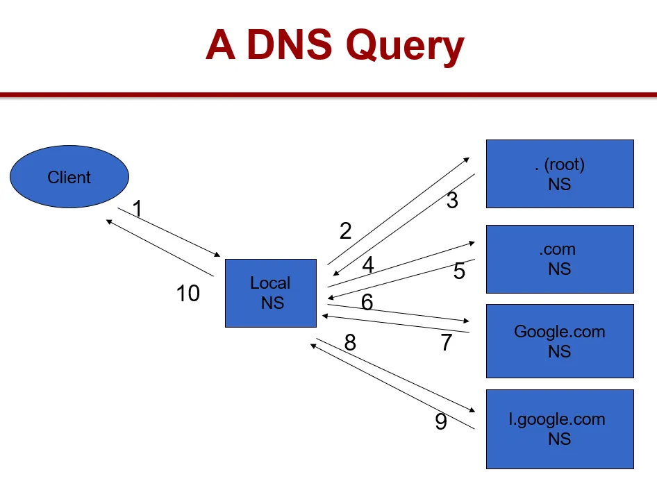
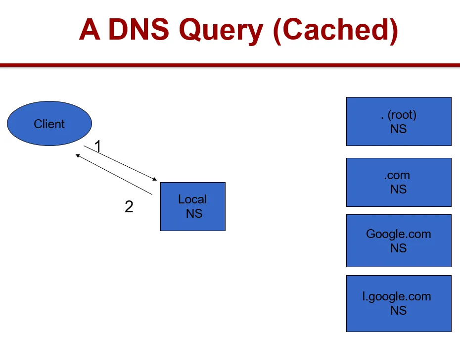
DNS Query Solution
-
Recursion
-
Ask a DNS server, get an answer
-
The server asks for information it does not have on your behalf
-
E.g. asking wpi.edu server about google.com that it doesn’t know about by default
-
-
Iteration
-
Server gives you an answer if it knows it
-
Otherwise gives a hint on where to look
-
E.g. asking root server for <www.wpi.edu> and it tells you to look under .edu
-
-
Recursion and Iteration both involved in a typical query
-
How it works
-
Operates at application layer
-
Most queries and responses operate over UDP
- How do we deal with being connectionless? ID field in DNS header
-
Zone transfer (receive all records from zone) operates over TCP
-
-
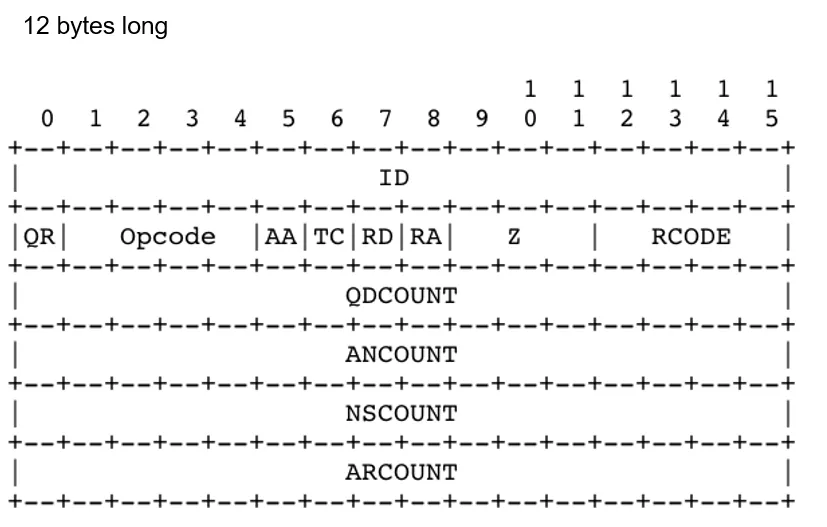
DNS Packet
-
Header
-
Question Section
-
Answer Section
- Answers to questions (initially blank)
-
Authority Section
- Who is the authority for these answers
-
Additional Section
- Such as location of Authority servers
-
-
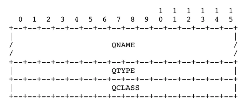
DNS Header Format
- Question Format
-
QNAME: What do we want to know about? Domain name usually
-
QTYPE: What type of records we want (e.g., A, CNAME, MX)
-
QCLASS: IN (Internet)
-
Example
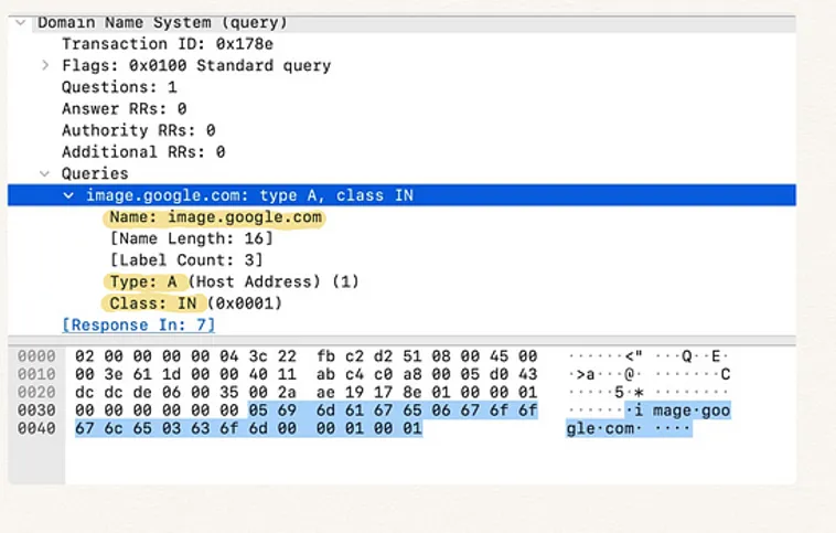
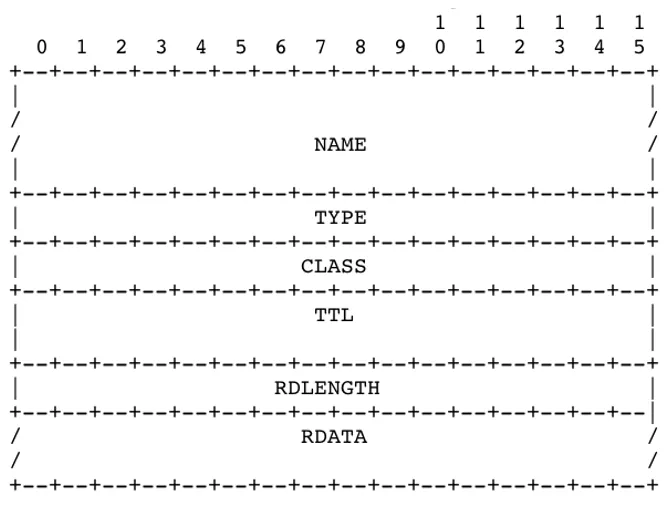
- Resource Record Format
-
Name: What is this record about?
-
TTL: How long is this record valid?
-
RDATA: The value of this record, content depends on type
-
Name format
-
255 total characters
-
Up to 10 labels, 63 characters each separated by ”.”
-
In DNS packet, labels separated by length fields
-
Example:
-
3www6google3com0
-
-
DNS Reverse Lookup
-
Reverse DNS lookup is the querying technique connecting the domain name with an IP address
- E.g.: An email server uses reverse DNS to validate the authenticity of an email. Many email servers reject messages not supported by reverse lookups.
-
Look up a name, given IP address
- Opposite of normal DNS
-
Requires additional DNS entries to work
-
PTR record type
-
A pointer that gives us the value
-
are stored in a specific zone as an “arpa”. A reverse DNS lookup is performed, functioning as an additional layer of email authentication.
-
-
Reverse IP address, and append
in-addr.arpa domain
(ip6.arpa for IPv6)A -
Example
-
Ex: Original IPv4 address 23.221.222.250 reversed is 250.222.221.23.
-
The new reversed IP address is concatenated to the domain in-addr.arpa, producing the PTR record 250.222.221.23.in-addr.arpa.
-
Ex: The PTR record 250.222.221.23.in-addr.arpa points to dns.wiley
-
If the A record for dns.wiley points back to 23.221.22.250 (the original IPv4 address), the reverse DNS lookup is considered forward-confirmed.
-
-
-
Cache Poisoning (simple attacks)
-
Unrelated data attack
- Just put any records you want in DNS packet - other DNS servers will believe them and cache them
-
Related data attack
-
Make the other records somehow related
- If I say google.com is my mail server, then it is valid for me to give you an address for it
-
-
-
Cache Poisoning (recursion based attacks)
-
ID guessing
-
With previous few IDs, guess next one
- I query server S for <www.google.com> recursively, causing it to query the google.com nameserver. I send a response to S with the correct ID before the real google.com server does.
-
Birthday attack
-
With enough simultaneous queries and enough guesses, can get ID correct with no previous information
-
50% success rate with only 300 queries and guesses
-
90% success rate with less than 600
-
-
-
-
-
Address Resolution Protocol (ARP)
-
Map between Internet address and hardware address
- Example: IPv4 to Ethernet MACs
-
Static Address Binding
- Create list of (IP, MAC) bindings and distribute
-
Dynamic Address Binding
- Use network to obtain and store these bindings
-
Allows A to find B’s MAC when A only knows B’s IP address
-
ARP is only for a local network
- Fails miserably for larger networks
-
Requestor uses hardware broadcast
-
Responder replies via unicast
-
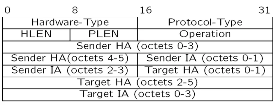
ARP Header
-
-
ARP Cache
-
ARP table is a simple cache
- Entries should be expired eventually
-
Problems
- What if nobody answers?
-
-
Reverse Address Resolution Protocol (RARP)
-
NOT to be confused with an ARP reply
-
RARP allows a requestor to find an Internet address given a hardware address
-
Why bother?
-
Diskless machines seeking their identities
-
Pretty much just legacy protocol now
-
-
-
Host Configuration
-
Hosts can have MAC addresses hardcoded in their interface cards
-
Why not do the same for IP addresses?
-
Do hosts need to be configured with anything other than their IP addresses?
-
Static
-
Real geeks use static configurations
-
Error prone
-
High administrative overhead
-
Mere mortals cannot hack static configuration
-
-
Dynamic
-
Central administration
-
Allows rapid updates
-
Allows address reusage (time multiplexing)
-
-
-
Dynamic host configuration protocol (DHCP)
-
a network management protocol used for automating the assignment of an IP address and network configuration parameters to devices on an IP network. DHCP components are:
-
A DHCP scope is an IP address range and network configuration parameters a DHCP server makes available to a DHCP client.
-
A DHCP server is a server configured to distribute a DHCP scope to a DHCP client.
-
A DHCP client is any device configured to receive a DHCP scope from a DHCP server.
-
-
DHCP saves network administrative resources compared to manually setting a networked device’s configuration. Common DHCP scope components are:
-
IP address
-
Subnet mask
-
Default gateway
-
DNS server address
-
-
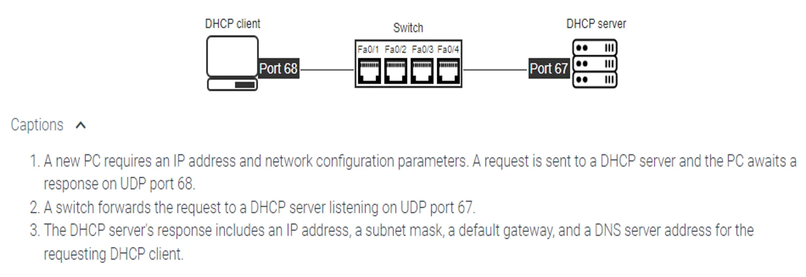
Example
-
-
Dynamic Host Control Protocol
-
Server responds to client requests and sends configuration information
-
Static DHCP
-
Uses MACs and deterministically provides IP
-
Great for servers
-
-
DHCP Pool
-
Uses a pool of addresses and assigns a free one to the requestor
-
Great for clients
-
-
Configure clients with DHCP server address?
-
Broadcast instead:
-
Issue a DISCOVER to find all DHCP servers
-
Some server OFFERs some configuration
-
Client REQUESTs a configuration it liked
-
The server ACKNOWLEDGEs the request
-
-
DHCP sits on top of UDP (port 67 for the server, 68 for the client)
- Any good reason why?
-
DHCP allocations are “leased” to allow reuse
- Half way to expiration, client attempts to renew
-
-
Internet Control Message Protocol (ICMP)
-
Mainly used for error reporting in IP
-
Can be issued by hosts or routers
-
Sits on top of IP at the transport layer
-
Some consider it a security risk
-
It may be blocked
-
Some participants may just not use it
-
-
Examples
-
Host unreachable
-
Fragment reassembly failure
-
Checksum failure
-
Router redirections
-
TTL value exceeded
- Remember a utility that exploits this?
-
Echo Request
- What could this be used for?
-
-
-
IP: The Next Generation
-
The address space has become an issue
-
4 billion addresses with 100% efficiency
-
Mobile devices, etc.
-
-
Requires a change to IP address headers
- Non-trivial, changes software everywhere (routers, end points, firewalls etc)
-
Everyone wanted to fix as many other things as they could in the new version
-
Most networks will still use IPv4 addresses in some capacity
-
-
What happened to IPv5?
-
Connection-oriented experiment
-
Parts of it ended up in MPLS
-
-
What does IPv6 do well?
-
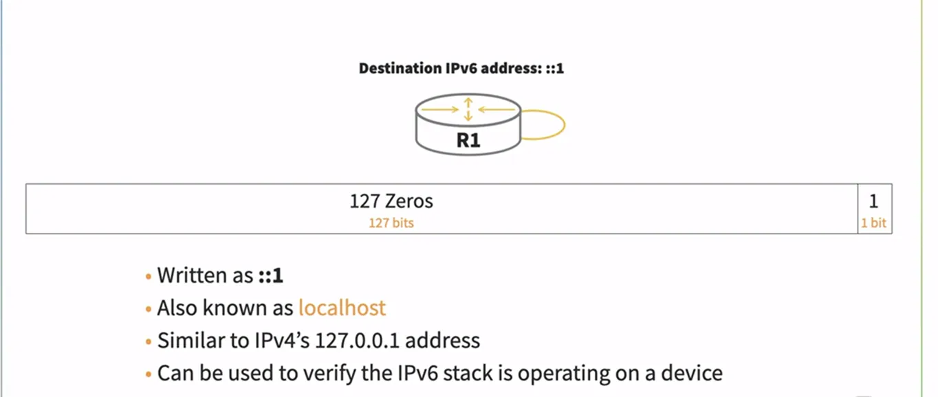
Addresses. And lots of them… 2^128
-
Auto-configuration
- Take MAC address and figure out your unique IPv6 address
-
Jumbograms
-
Better options processing
-
-
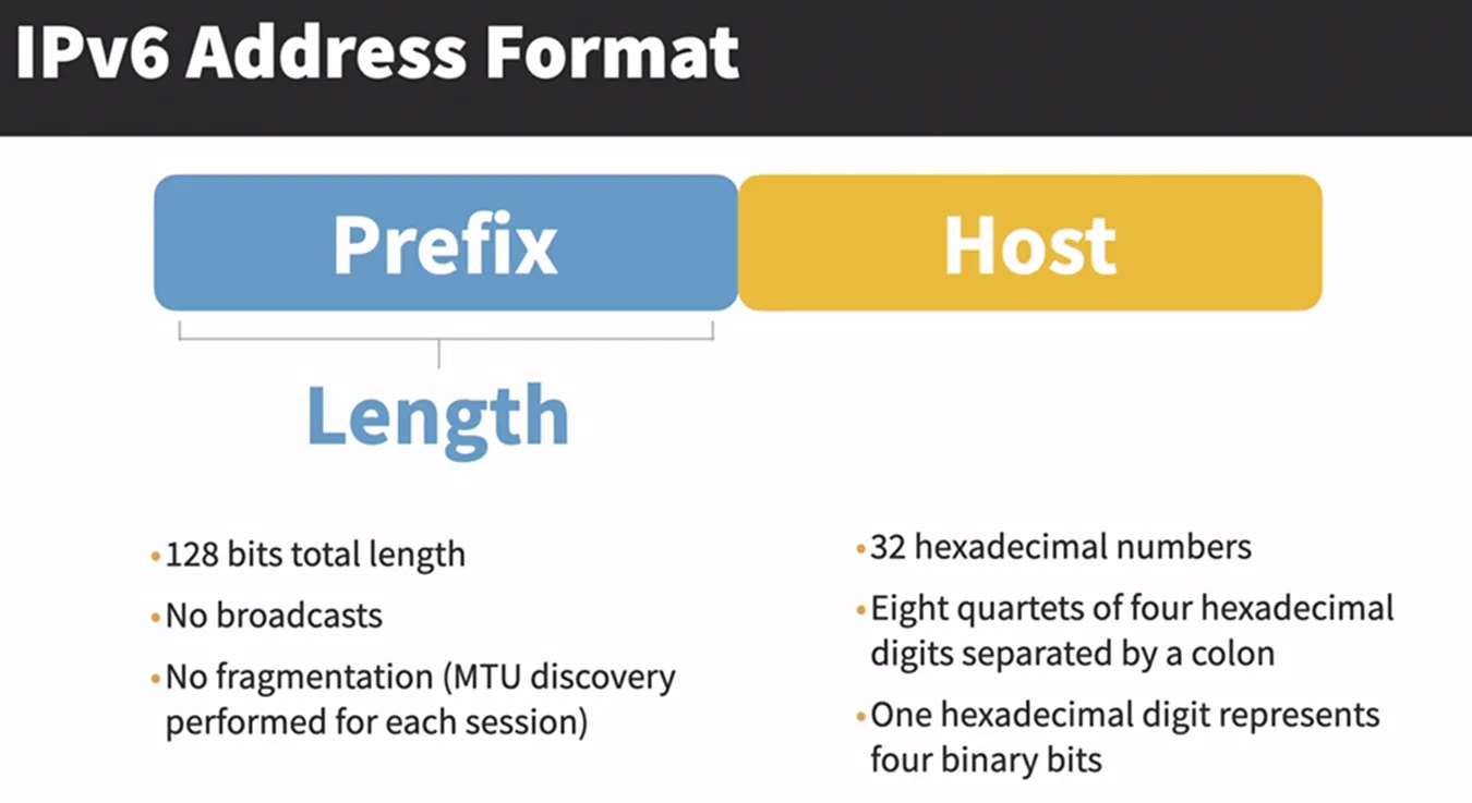
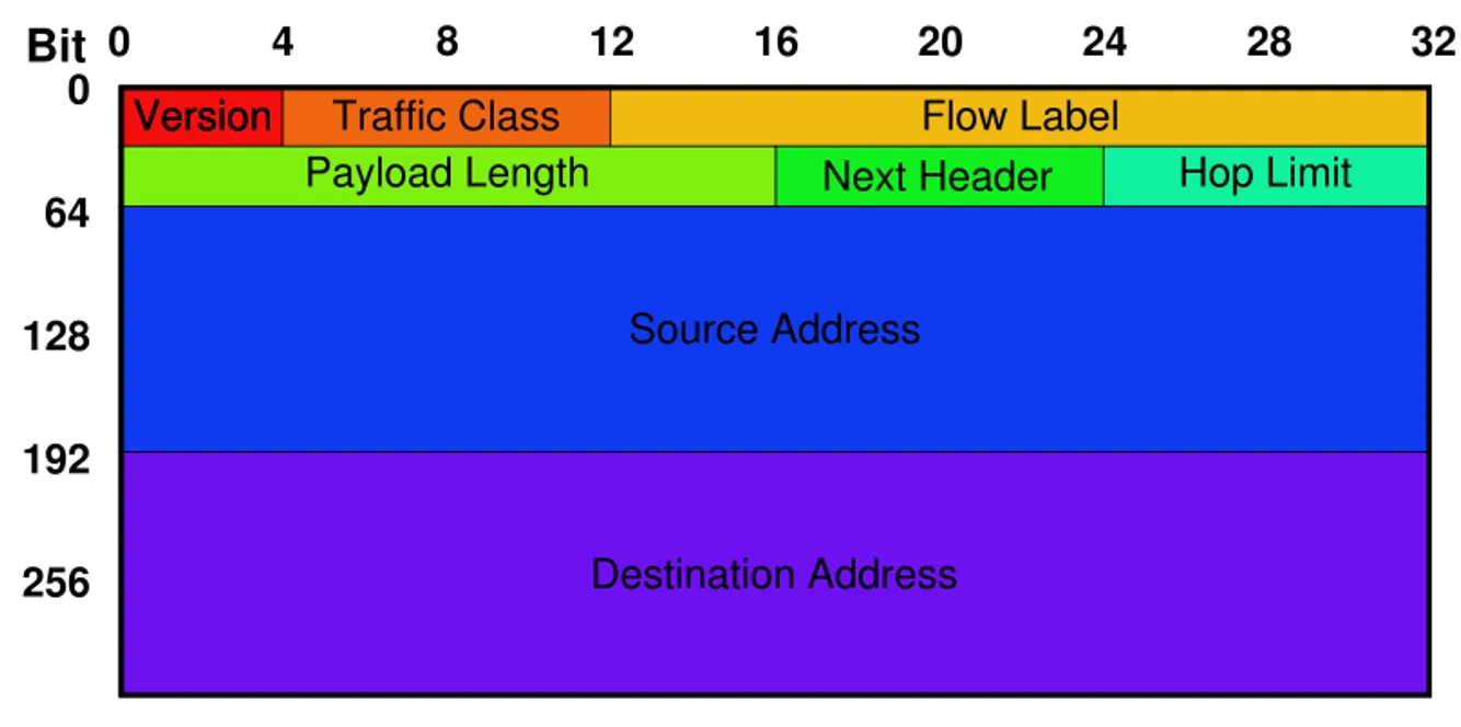
IPv6 Header
-
Version field, which is set to 6 for IPv6. The Version field is in the same place relative to the start of the header as IPv4’s Version field so that header-processing software can immediately decide which header format to look for.
-
The TrafficClass and FlowLabel fields both relate to quality of service issues.
-
The PayloadLen field gives the length of the packet, excluding the IPv6 header, measured in bytes.
-
The NextHeader field cleverly replaces both the IP options and the Protocol field of IPv4. If options are required, then they are carried in one or more special headers following the IP header, and this is indicated by the value of the NextHeader field.
-
If there are no special headers, the NextHeader field is the demux key identifying the higher-level protocol running over IP (e.g., TCP or UDP); that is, it serves the same purpose as the IPv4 Protocol
-
Also, fragmentation is now handled as an optional header, which means that the fragmentation-related fields of IPv4 are not included in the IPv6 header
-
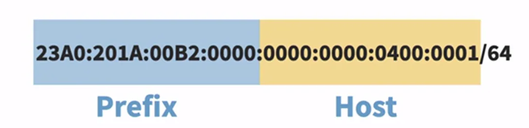
IPv6 Addresses
-
Dotted decimal? Make room for hex!
- 2001:0db8:85a3:08d3:1319:8a2e:0370:7334
-
Special notation rules
-
Drop leading zeros
-
Drop groups of zeros
-
All of these are valid:
2001:0db8:0000:0000:0000:0000:1428:57ab 2001:0db8:0000:0000:0000::1428:57ab 2001:0db8:0:0::1428:57ab
2001:0db8::1428:57ab
2001:db8::1428:57ab
-
-
-
IPv6 Address Space Resolution
-
Vast majority is reserved for future use
-
Aggregatable Global Unicast Addresses make up 1/8 of all addresses
-
“Link local use” addresses are usable on local network, but not globally unique
- Autoconfiguration
-
“Site local use” is used by private networks
-
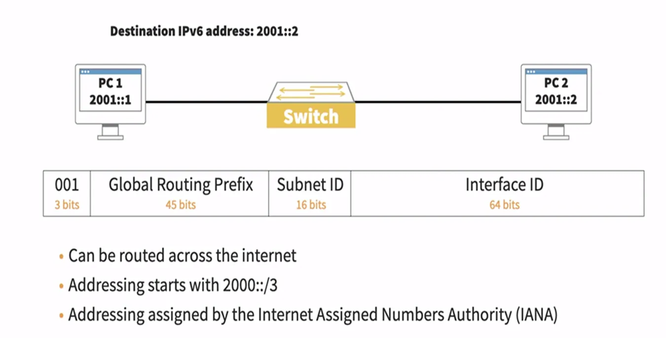
3 bits for “Global Unicast Address”: 001
-
Registry ID — Various registrars per country/continent
-
Provider ID — Transit network provider (e.g. MCI, ATT, Sprint)
-
Subscriber ID — Smaller ISP (e.g. Insight)
-
Subnet ID — Identifies smaller networks
-
Interface ID — Used to identify hosts, routers, etc.
-
IPv6 Global Unicast (example)
-
- IPv6 Loopback
-
Advanced Capabilities
-
IPv6 Deployment
-
Who uses it?
- Nobody?
-
Adoption is very slow, but Africa, Japan, China and US governments are switching to it
-
Why isn’t it being used more?
-
NAT
-
CIDR
-
Unequal distribution leaves the US in good shape
-
-
-
Internet2
-
What is Internet2?
-
The Internet on steroids?
-
The Internet running IPv6?
-
Just a media term like “information super-highway”?
-
A great place for p2p software?
-
-
No. Well, maybe the last one…
-
A coalition of 208 universities and partners in industry and government
-
Isn’t there a network though?
-
Yes, previously the Abilene Backbone Network, now simply “Internet2”
-
Indiana University manages Internet2
-
-
-
Routing
-
“Routing” vs. “Forwarding”
-
Control Plane — Routing (finding the appt path to reach the destination — populate the table to forward a packet)
-
Data Plane — Forwarding (which interface to forward the data out of — using a lookup table)
-
Analogy: Assembly line
-
-
Does it scale?
-
Intra-domain — Small network
-
Inter-domain — Links networks together
-
-
Routing among ISPs today: Border Gateway Protocol (BGP)
-
Network Routing or Graph Theory?
-
Network as a graph
-
Nodes = routers
-
Edges have cost
-
-
Calculate shortest path and store it
-
Node/Link Failures?
-
New nodes/links?
-
No changes in cost to reflect load
-
-
Distributed routing algorithms
-
Centralized doesn’t scale, but distributed is hard
-
Convergence/agreement essential. Why?
-
-
-
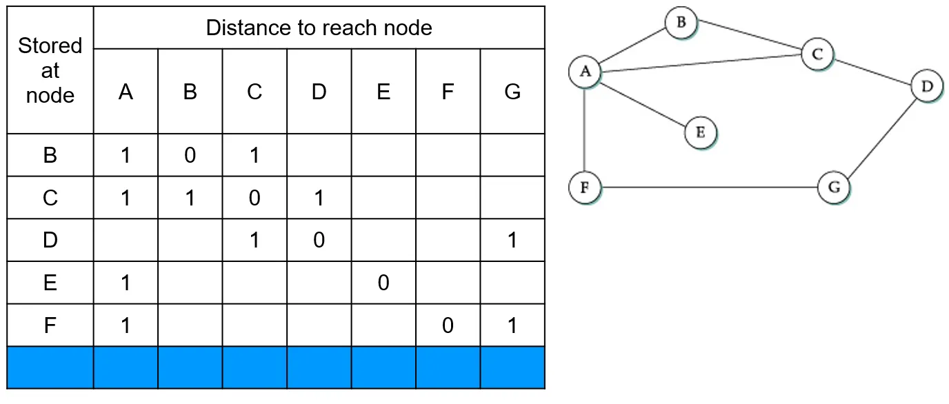
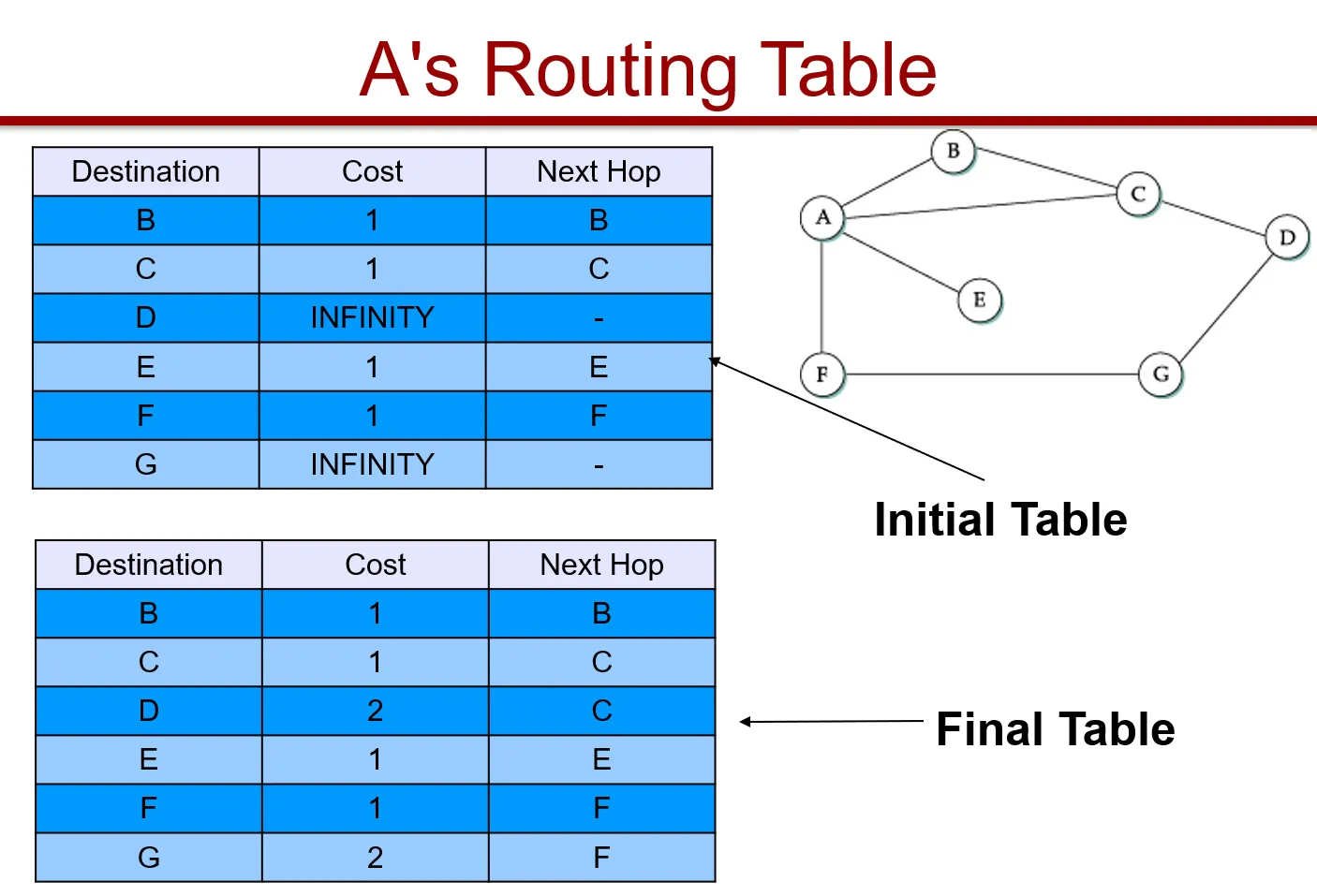
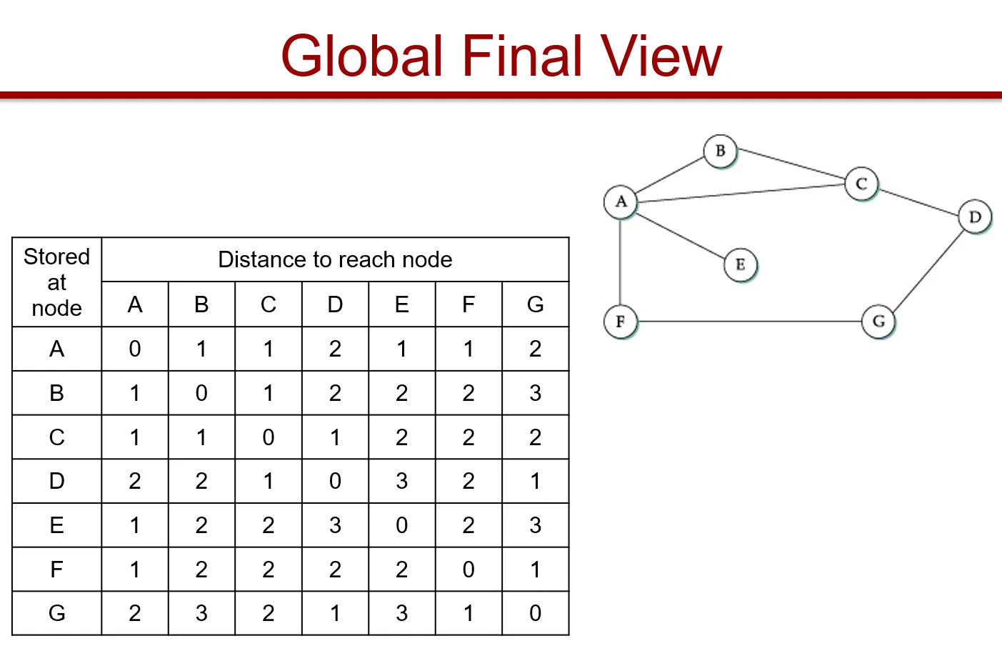
Distance Vector (RIP)
- Nodes create an array/vector with costs to all other nodes, then share this with neighbors
-
-
Periodic updates (seconds to minutes)
-
Triggered updates (update causes a change)
- Cascades to neighbors (and recalculate)
-
Detecting failures
- Soft-state (pings), inactivity (misses update cycles)
-
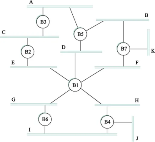
What happens when link F to G fails?
-
What happens when link A to E fails?
- Count to infinity!
-
Bound infinity to 16
- Any problems?
-
Split Horizon
- Don’t include advertisements of a route back to its source (e.g., if you learned from A, don’t tell A)
-
Split Horizon with Poison Reverse
- Include the route back, but poison with infinity
-
Split horizons only work with two node loops
-
Drastic measures: Simply delay after failures
- Slows down convergence
-
Routing Information Protocol (RIP)
-
Uses distance vector routing
-
Instead of calculating costs to nodes, calculates costs to reach attached networks
-
<Network-address, distance>
pairs -
RIP advertisements every 30 secs
-
Can support more than just IPv4
-
RIPv2 adds scalability features
-
Each link has a cost of 1; 16 = infinity
-
-
Network Layer: Control Plane
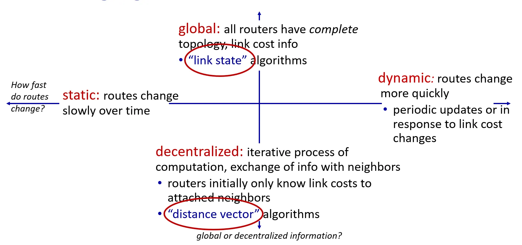
- Routing algorithm classification
-
Routing algorithms
-
Link state
-
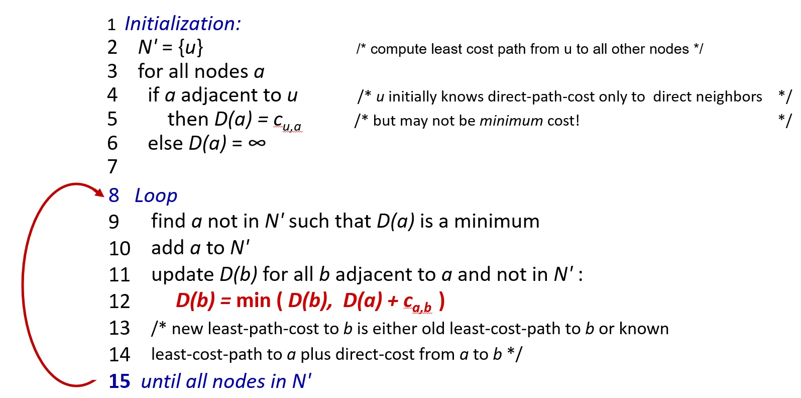
Dijkstra’s link-state routing algorithm
-
centralized: network topology, link costs known to all nodes
-
accomplished via “link state broadcast”
-
all nodes have same info
-
-
computes least cost paths from one node (“source”) to all other nodes
- gives forwarding table for that node
-
iterative: after k iterations, know least cost path to k destinations
-
-
Notation
-
Ca,b: direct link cost from node a to b; = ∞ if not direct neighbors
-
D(a): current estimate of cost of least-cost-path from source to destination a
-
p(a): predecessor node along path from source to a
-
N’: set of nodes whose least-cost-path definitively known
-
-
-
-
Distance vector
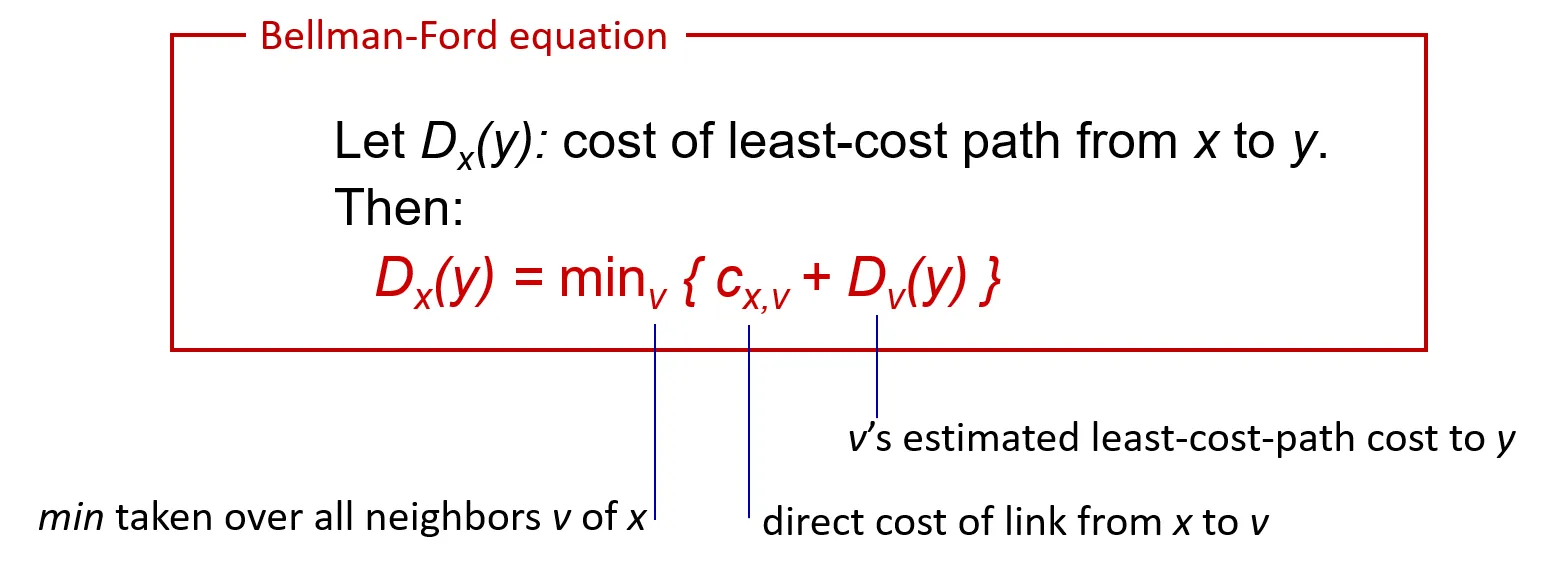
- Based on Bellman-Ford (BF) equation (dynamic programming):
-
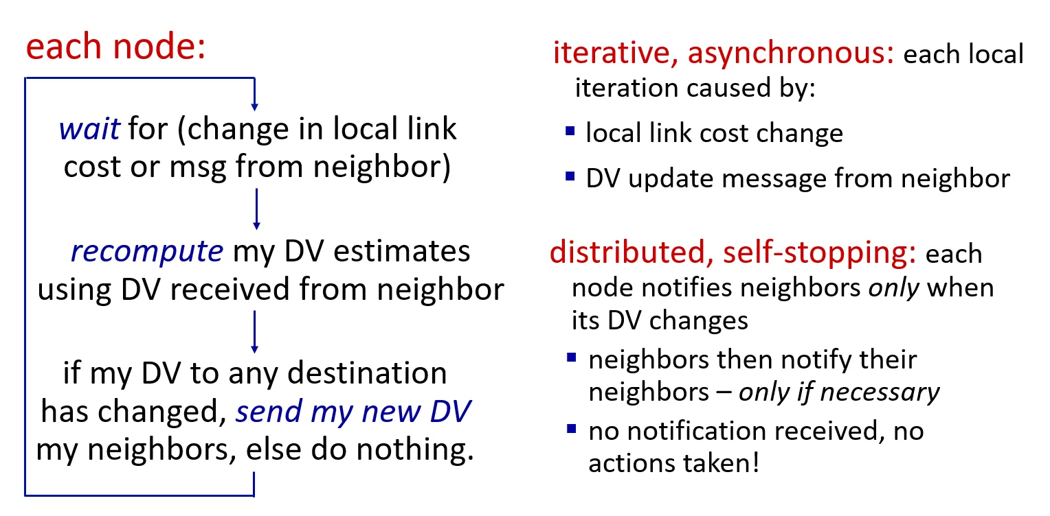
key idea:
- from time-to-time, each node sends its own distance vector estimate to neighbors
-
when x receives new DV estimate from any neighbor, it updates its own DV using B-F equation:
- Dx(y) ← minv{cx,v + Dv(y)} for each node y ∊ N
-
under minor, natural conditions, the estimate Dx(y) converge to the actual least cost dx(y)
-
Comparison of link state and distance vector algorithms
-
message complexity
-
LS: n routers, O(n^2) messages sent
-
DV: exchange between neighbors; convergence time varies
-
-
speed of convergence
-
LS: O(n^2) algorithm, O(n^2) messages
- may have oscillations
-
DV: convergence time varies
-
may have routing loops
-
count-to-infinity problem
-
-
-
robustness: what happens if router malfunctions, or is compromised?
-
LS:
-
router can advertise incorrect link cost
-
each router computes only its own table
-
-
DV:
-
DV router can advertise incorrect path cost (“I have a really low-cost path to everywhere”): black-holing
-
each router’s DV is used by others: error propagate thru network
-
-
-
-
intra-ISP routing: OSPF
-
our routing study thus far: idealized
-
all routers identical
-
network “flat”
-
… not true in practice
-
-
scale: billions of destinations:
-
can’t store all destinations in routing tables!
-
exchanging link-state or DV information would swamp links!
-
-
administrative autonomy:
-
Internet: a network of networks
-
each network admin may want to control routing in its own network
-
-
Internet approach to scalable routing
-
aggregate routers into regions known as “autonomous systems” (AS) (a.k.a. “domains”)
-
intra-AS (aka “intra-domain”): routing among routers within same AS (“network”)
-
all routers in AS must run same intra-domain protocol
-
routers in different AS can run different intra-domain routing protocols
-
gateway router: at “edge” of its own AS, has link(s) to router(s) in other AS’es
-
-
inter-AS (aka “inter-domain”): routing among AS’es
- gateways perform inter-domain routing (as well as intra-domain routing)
-
-
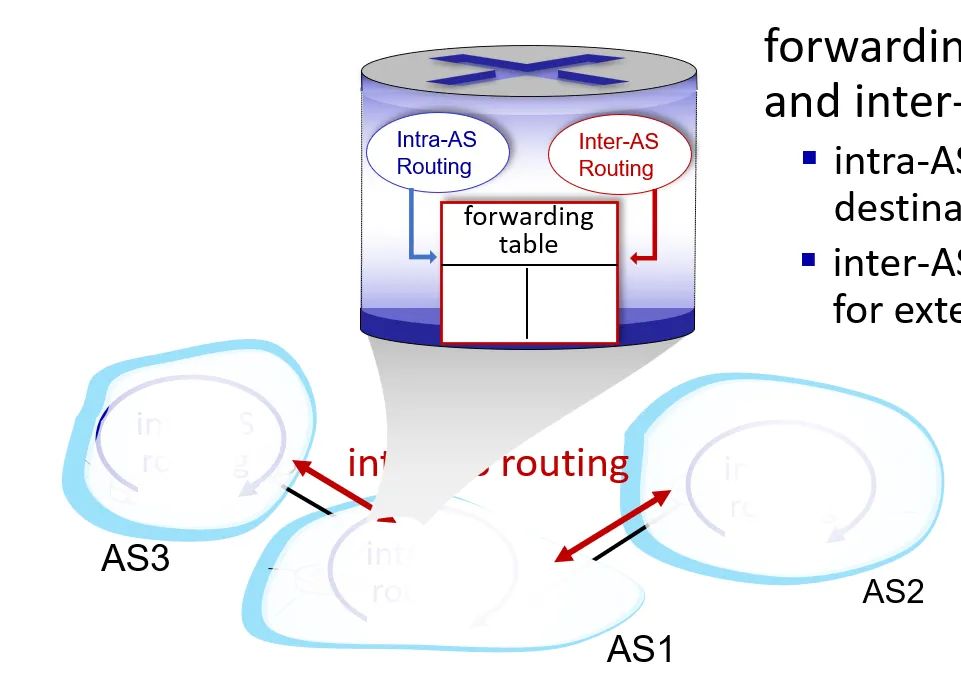
Interconnected ASes
-
forwarding table configured by intra- and inter-AS routing algorithms
-
intra-AS routing determine entries for destinations within AS
-
inter-AS & intra-AS determine entries for external destinations
-
-
-
-
Inter-AS routing: routing within an AS
-
most common intra-AS routing protocols:
-
RIP: Routing Information Protocol [RFC 1723]
-
classic DV: DVs exchanged every 30 secs
-
no longer widely used
-
-
OSPF: Open Shortest Path First [RFC 2328]
- classic link-state routing
-
EIGRP: Enhanced Interior Gateway Routing Protocol
-
DV based
-
formerly Cisco-proprietary for decades
-
became open in 2013 [RFC 7868])
-
-
-
OSPF
-
“open”: publicly available
-
classic link-state
-
each router floods OSPF link-state advertisements (directly over IP rather than using TCP/UDP) to all other routers in entire AS
-
multiple link costs metrics possible: bandwidth, delay
-
each router has full topology, uses Dijkstra’s algorithm to compute forwarding table
-
-
security: all OSPF messages authenticated (to prevent malicious intrusion)
-
-
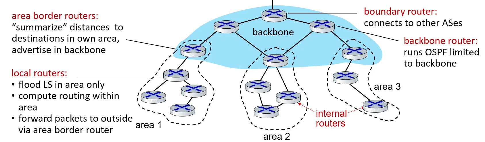
Hierarchical OSPF
-
two-level hierarchy: local area, backbone.
-
link-state advertisements flooded only in area, or backbone
-
each node has detailed area topology; only knows direction to reach other destinations
-
-
-
inter-ISP routing: BGP
-
BGP (Border Gateway Protocol): the de facto inter-domain routing protocol
- “glue that holds the Internet together”
-
allows subnet to advertise its existence, and the destinations it can reach, to rest of Internet: “I am here, here is who I can reach, and how”
-
BGP provides each AS a means to:
-
obtain destination network reachability info from neighboring ASes determine routes to other networks based on reachability information and policy (something like avoiding a certain ISP or even a country)
-
propagate reachability information to all AS-internal routers advertise (to neighboring networks) destination reachability info or may be not?
-
-
BGP basics
-
BGP session: two BGP routers (“peers, speakers”) exchange BGP messages over semi-permanent TCP connection port 179:
-
advertising paths to different destination network prefixes (e.g., to a destination /16 network)
-
BGP is known as a “path vector” protocol
-
-
-
-
BGP protocol messages
-
BGP messages exchanged between peers over TCP connection
-
BGP messages [RFC 4371]:
-
OPEN: opens TCP connection to remote BGP peer and authenticates sending BGP peer
-
UPDATE: advertises new path (or withdraws old)
-
KEEPALIVE: keeps connection alive in absence of UPDATES; also ACKs OPEN request
-
NOTIFICATION: reports errors in previous msg; also used to close connection
-
-
-
Path attributes and BGP routes
-
BGP advertised path: prefix + attributes
-
path prefix: destination being advertised
-
two important attributes:
-
AS-PATH: list of ASes through which prefix advertisement has passed
-
NEXT-HOP: indicates specific internal-AS router to next-hop AS
-
-
-
policy-based routing:
-
router receiving route advertisement to destination X uses policy to accept/reject a path (e.g., never route through AS W, or country Y).
-
router uses policy to decide whether to advertise a path to neighboring AS Z (does router want to route traffic forwarded from Z destined to X?)
-
-
-
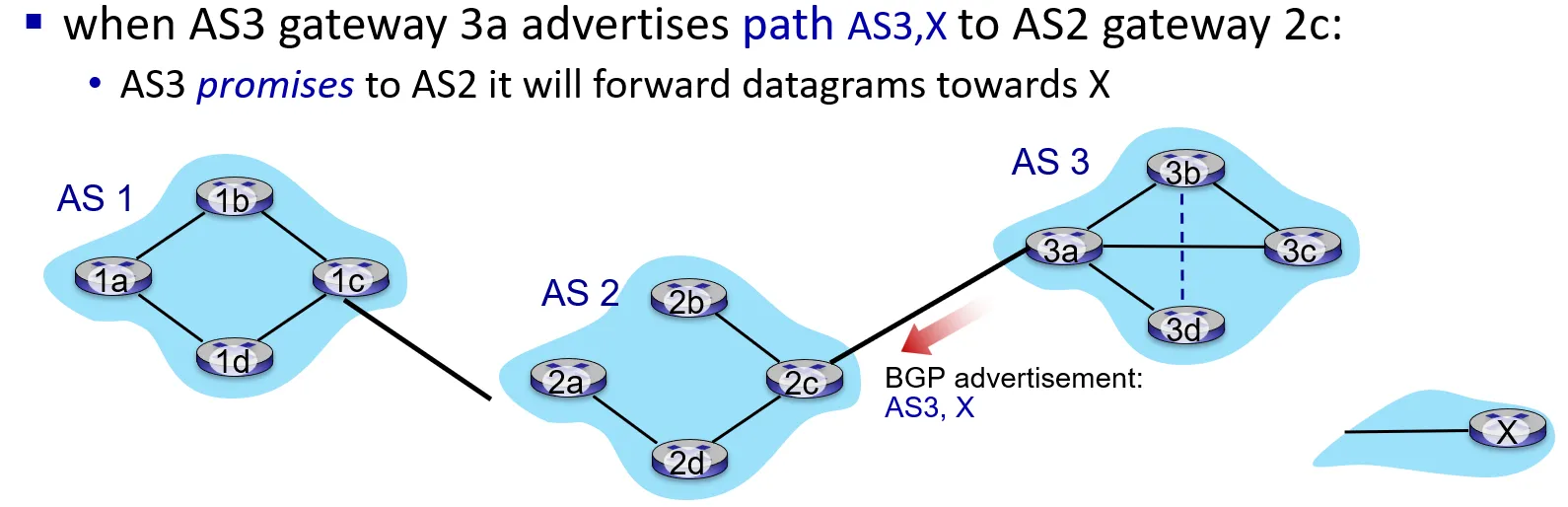
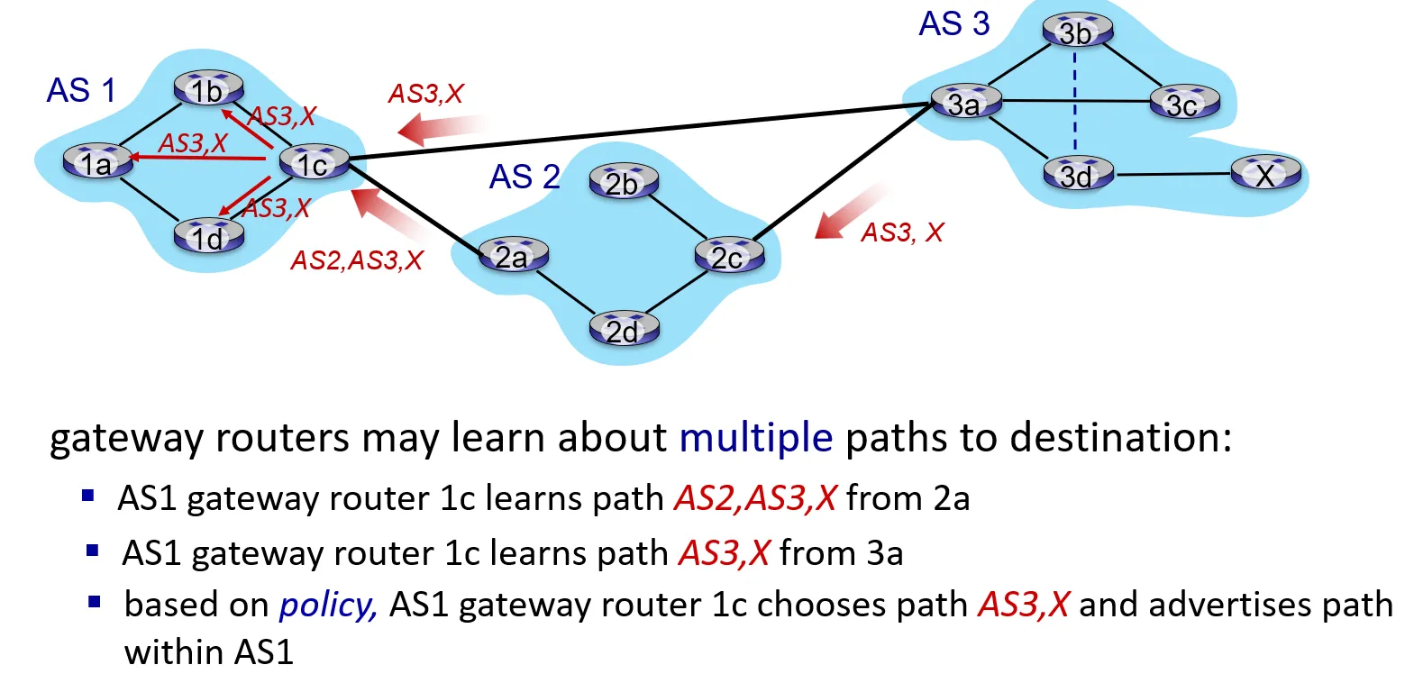
BGP path advertisement
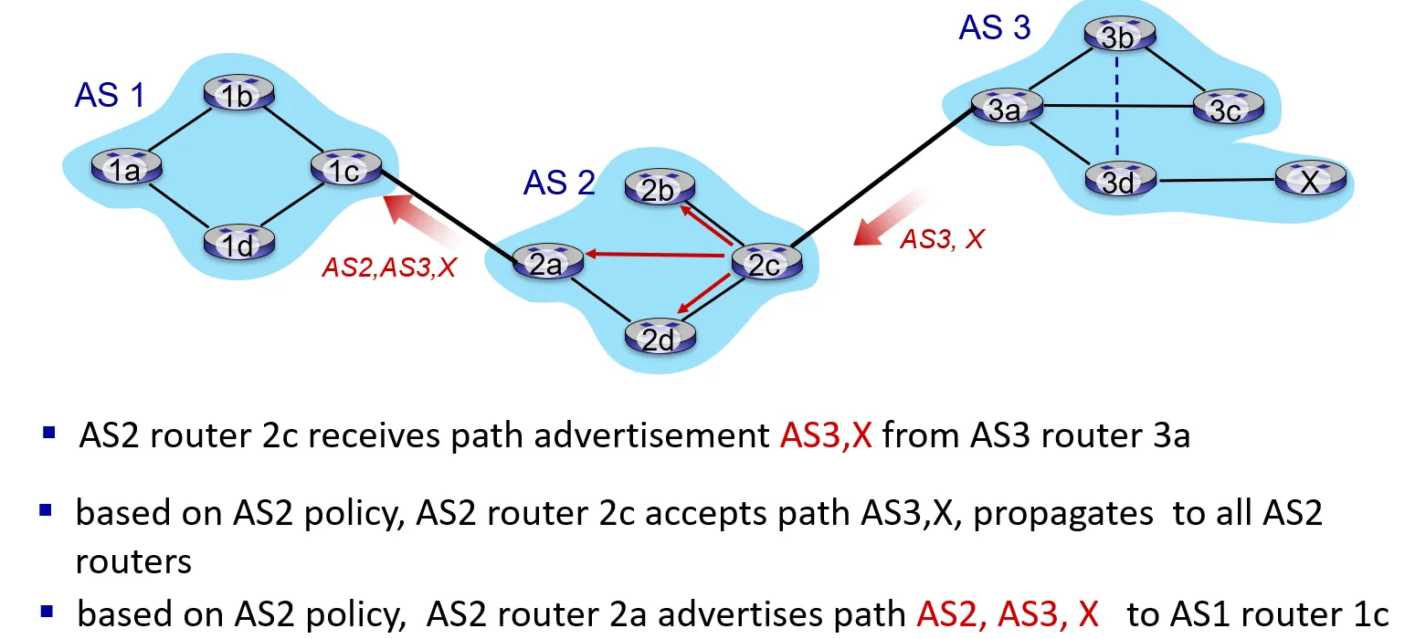
- BGP path advertisement: multiple paths
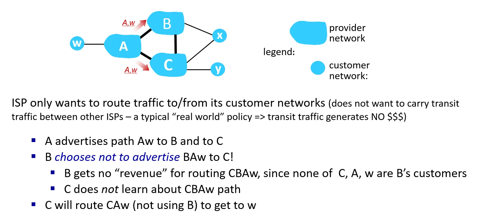
- BGP: achieving policy via advertisements
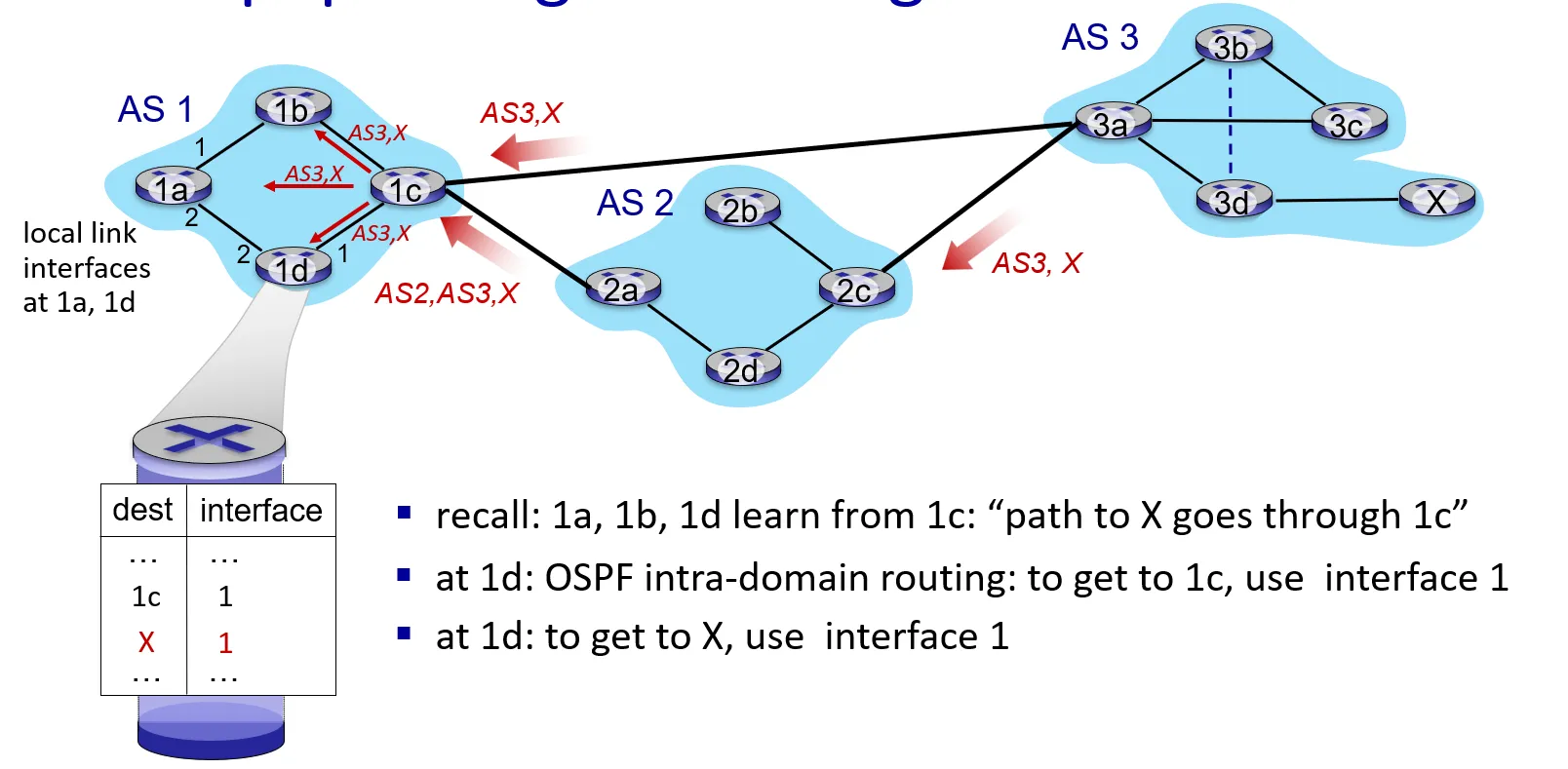
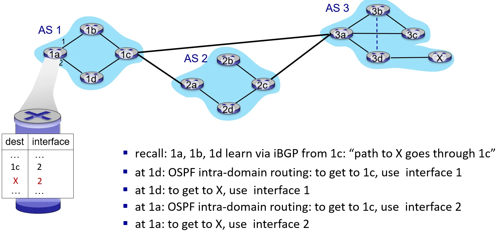
- BGP: populating forwarding tables
- Hot potato routing
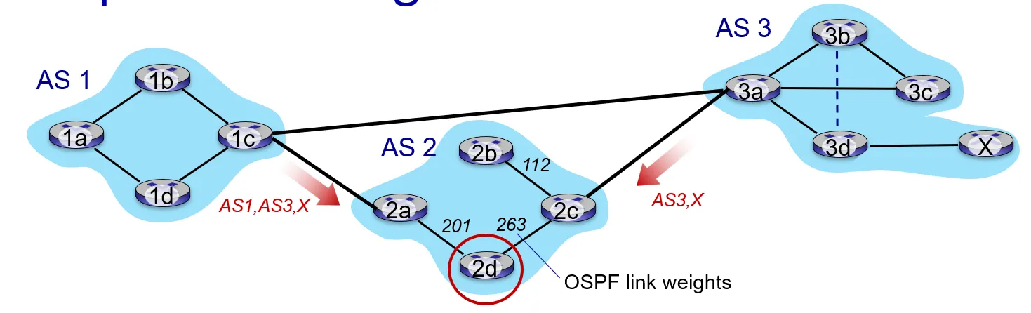
-
2d learns it can route to X via 2a or 2c
-
hot potato routing: choose local gateway that has least intra-domain cost (e.g., 2d chooses 2a, even though more AS hops to X): don’t worry about inter-domain cost!
-
Why different infra-, inter-AS routing?
-
policy:
-
inter-AS: admin wants control over how its traffic routed, who routes through its network
-
intra-AS: single admin, so policy less of an issue
-
-
scale: reducing forwarding table size, routing update traffic
- hierarchical routing: limiting the scope of full topological information
-
performance:
-
intra-AS: can focus on performance
-
inter-AS: policy dominates over performance
-
-
-
Network Layer: Data Plane
-
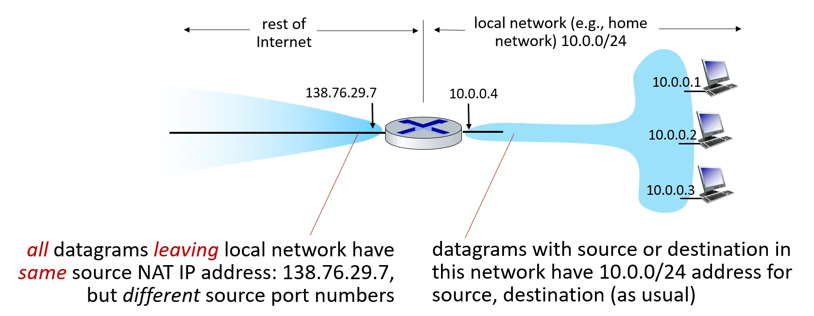
NAT (Network Adress Transmission)
- All devices in local network share just one IPv4 address as far as outside world is concerned
-
-
all devices in local network have 32-bit addresses in a “private” IP address space (10/8, 172.16/12, 192.168/16 prefixes) that can only be used in local network
-
advantages:
-
just one IP address needed from provider ISP for all devices
-
can change addresses of host in local network without notifying outside world
-
can change ISP without changing addresses of devices in local network
-
security: devices inside local net not directly addressable, visible by outside world
-
-
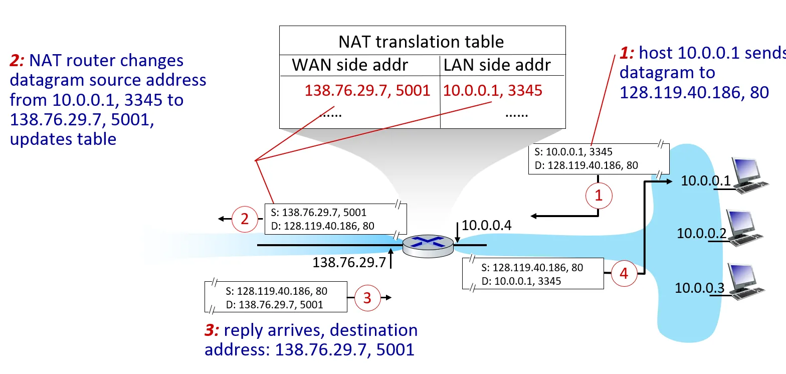
implementation: NAT router must (transparently):
-
outgoing datagrams: replace (source IP address, port #) of every outgoing datagram to (NAT IP address, new port #)
- remote clients/servers will respond using (NAT IP address, new port #) as destination address
-
remember (in NAT translation table) every (source IP address, port #) to (NAT IP address, new port #) translation pair
-
incoming datagrams: replace (NAT IP address, new port #) in destination fields of every incoming datagram with corresponding (source IP address, port #) stored in NAT table
-
-
Example
-
NAT has been controversial:
-
address “shortage” should be solved by IPv6
-
violates end-to-end argument (port # manipulation by network-layer device)
-
NAT traversal: what if client wants to connect to server behind NAT?
-
-
but NAT is here to stay:
- extensively used in home and institutional nets, 4G/5G cellular nets
-
Transport Layer
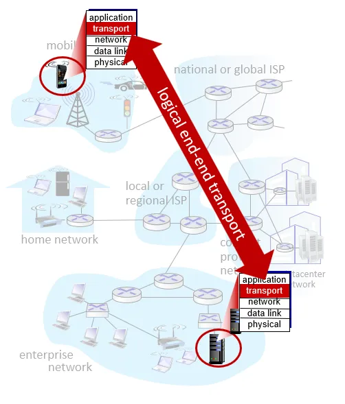
- Transport services and protocols
-
provide logical communication between application processes running on different hosts
-
transport protocols actions in end systems:
-
sender: breaks application messages into segments, passes to network layer
-
receiver: reassembles segments into messages, passes to application layer
-
-
two transport protocols available to Internet applications
- TCP, UDP
-
Transport vs. network layer services and protocols
-
network layer: logical communication between hosts
-
transport layer: logical communication between processes
- relies on, enhances, network layer services
-
Analogy
-
12 kids in Ann’s house sending letters to 12 kids in Bill’s house:
-
hosts = houses
-
processes = kids
-
app messages = letters in envelopes
-
transport protocol = Ann and Bill who demux to in-house siblings
-
network-layer protocol = postal service
-
-
-
Transport Layer Actions
-
Sender:
-
is passed an application-layer message
-
determines segment header fields values
-
creates segment
-
passes segment to IP
-
-
Receiver:
-
receives segment from IP
-
checks header values
-
extracts application-layer message
-
demultiplexes message up to application via socket
-
-
-
Two principal Internet transport protocols
-
TCP: Transmission Control Protocol
-
reliable, in-order delivery
-
congestion control
-
flow control
-
connection setup
-
-
UDP: User Datagram Protocol
-
unreliable, unordered delivery
-
no-frills extension of “best-effort” IP
-
-
services not available:
-
delay guarantees
-
bandwidth guarantees
-
-
-
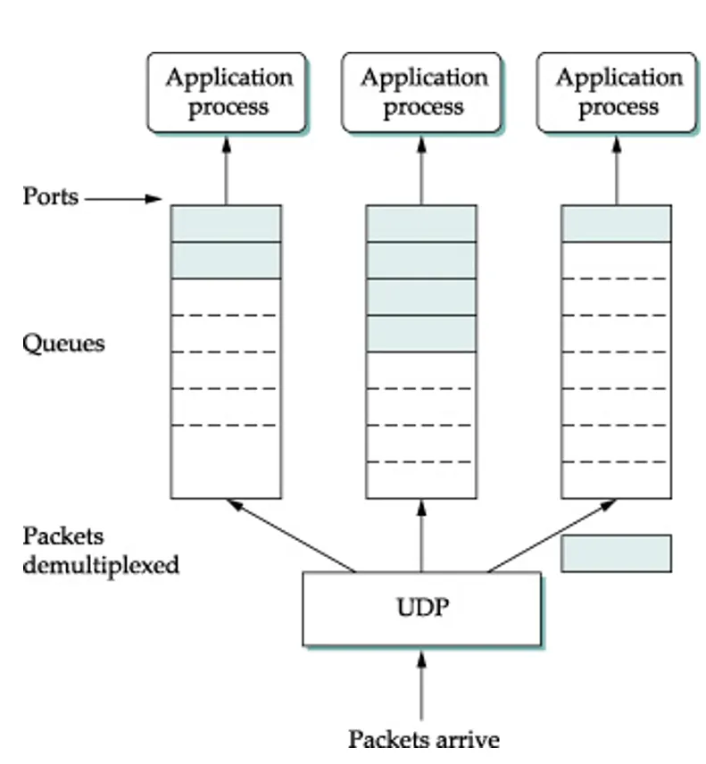
Multiplexing and demultiplexing
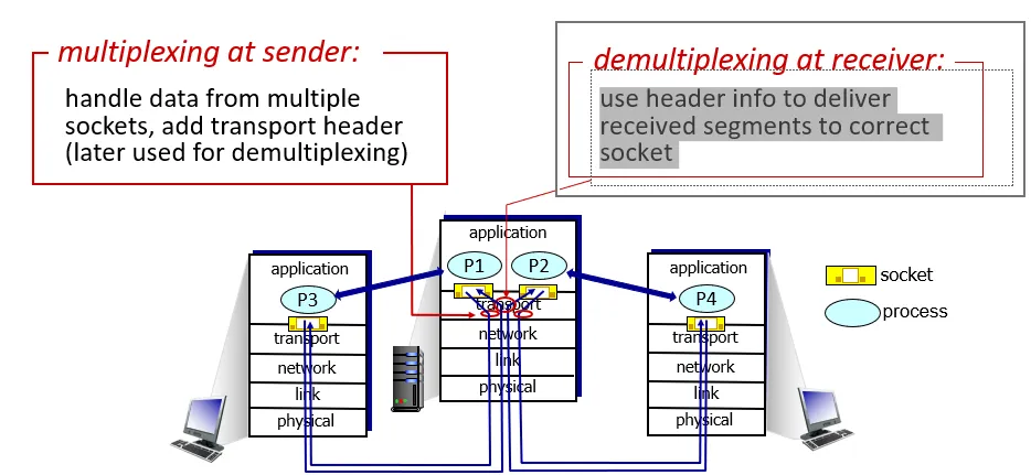
-
How demultiplexing works
-
host receives IP datagrams
-
each datagram has source IP address, destination IP address
-
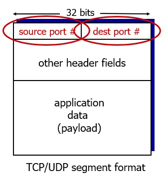
each datagram carries one transport-layer segment
-
each segment has source, destination port number
-
-
host uses IP addresses & port numbers to direct segment to appropriate socket
-
-
Connectionless demultiplexing
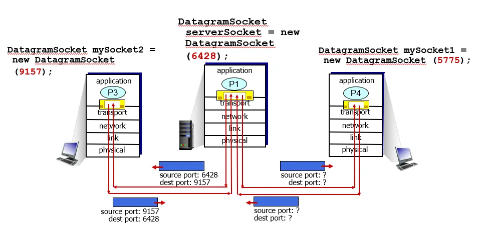
-
Recall:
- when creating socket, must specify host-local port #:
-
DatagramSocket mySocket1 = new DatagramSocket(12534);
-
when creating datagram to send into UDP socket, must specify
-
destination IP address
-
destination port #
-
-
when receiving host receives UDP segment:
-
checks destination port # in segment
-
directs UDP segment to socket with that port #
-

-
IP/UDP datagrams with same dest. port #, but different source IP addresses and/or source port numbers will be directed to same socket at receiving host
-
Connection-oriented demultiplexing
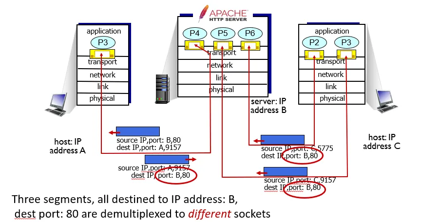
-
TCP socket identified by 4-tuple:
-
source IP address
-
source port number
-
dest IP address
-
dest port number
-
-
demux: receiver uses all four values (4-tuple) to direct segment to appropriate socket
-
server may support many simultaneous TCP sockets:
-
each socket identified by its own 4-tuple
-
each socket associated with a different connecting client
-
-
-
Connetionless transport: UDP (User Datagram Protocol)
-
“no frills,” “bare bones” Internet transport protocol
-
“best effort” service, UDP segments may be:
-
lost
-
delivered out-of-order to app
-
-
connectionless:
-
no handshaking between UDP sender, receiver
-
each UDP segment handled independently of others
-
-
Why is there UDP?
-
no connection establishment (which can add RTT delay)
-
simple: no connection state at sender, receiver
-
small header size
-
no congestion control
-
UDP can blast away as fast as desired!
-
can function in the face of congestion
-
-
-
UDP use:
-
streaming multimedia apps (loss tolerant, rate sensitive)
-
DNS
-
SNMP
- used to monitor and manage network devices connected over an IP. SNMP is used for communication between routers, switches, firewalls, load balancers, servers, CCTV cameras, and wireless devices.
-
HTTP/3
-
-
if reliable transfer needed over UDP (e.g., HTTP/3):
-
add needed reliability at application layer
-
acc congestion control at application layer
-
-
Transport layer actions:
-
Sender:
-
is passed an application-layer message
-
determines UDP segment header fields values
-
Creates UDP segment
-
Passes segment to IP
-
-
Receiver:
-
Receives segment from IP
-
Checks UDP checksum header value
-
Extracts application-layer message
-
Demultiplexes message up to application via socket
-
-
-
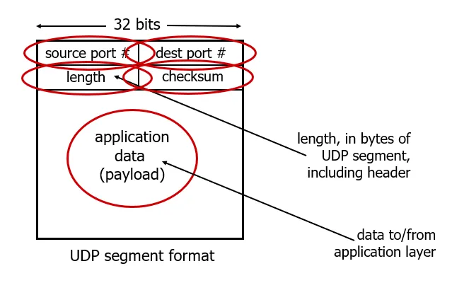
UDP segment header
-
-
UDP checksum
-
Goal: detect errors (i.e., flipped bits) in transmitted segment
-
sender:
-
treat contents of UDP segment (including UDP header fields and IP addresses) as sequence of 16-bit integers
-
checksum: addition (one’s complement sum) of segment content
-
checksum value put into UDP checksum field
-
-
receiver:
-
compute checksum of received segment
-
check if computed checksum equals checksum field value:
-
Not equal - error detected
-
Equal - no error detected. But maybe errors nonetheless? More later …
-
-
-
User Datagram Protocol (UDP)
-
Provides applications with ability to send and receive datagrams
-
Provides for multiple concurrent applications on a single machine
-
Includes an optional checksum field
-
Unreliable, connectionless protocol
-
Details
-
Defines format of messages sent
-
Message includes small integer ports to demultiplex
-
Messages encapsulated
in IP
-
-
-
Transmission Control Protocol (TCP)
-
Major transport service in the TCP/IP suite
-
Reliable transfer
-
Stream paradigm
-
Full duplex connections
-
Flow control
-
Uses IP for transmission
-
TCP Details
-
Allows sender to generate a stream of bytes in convenient chunks
-
Divides stream into small segments for transmission
-
Sends each segment in IP datagram
-
Receiving TCP returns acknowledgment upon successful receipt of data
-
Sender starts timer after segment sent and retransmits unless positive acknowledgment arrives
-
Segment contains checksum for data being sent
-
Receiver acknowledges highest byte received, not each specific segment
-
Protocol port numbers used to distinguish multiple applications
-
Receiver controls flow by telling the sender the size of the available buffer (a window advertisement)
-
Each segment contains the advertisement
-
Receiver can send additional acknowledgments whenever buffer space becomes available
-
Data flow may be shut down in one direction
-
Connections started reliably and terminated gracefully
-
-
TCP Retransmission
-
Designed for Internet environment
-
Delays on one connection vary over time
-
Delays vary widely between connections
-
-
Fixed value for timeout will fail
-
Waiting too long introduces needless delay
-
Not waiting long enough means unnecessary retransmissions
-
-
Retransmission must be adaptive
-
-
Adaptive retransmission
-
TCP keeps estimates of round-trip time on each connection
-
This estimate derived from observed delay between sending a segment and receiving of the acknowledgment
-
Timeout for retransmission based on current round-trip estimate
-
These are heuristics and can sometimes fail
-
-
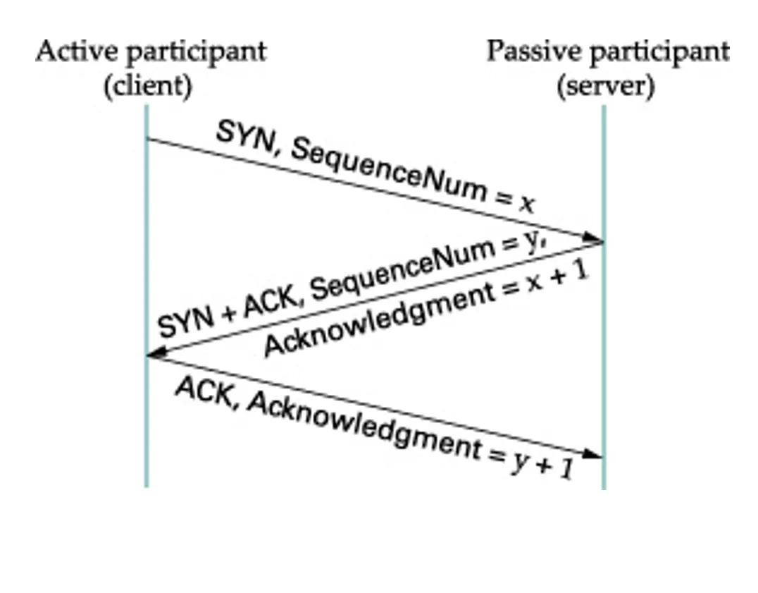
Three Way Handshake for Connection Start-up
-
-
Assignment of Protocol Ports
-
Need globally fixed ports for globally-known services
-
Need dynamically allocated ports for other services
-
Accommodate with two port types
-
Statically assigned ports
-
Dynamically assigned ports
-
-
Note: servers use statically assigned ports; clients use dynamically assigned ports
-
-
Statically Assigned Ports
-
Called “well-known”
-
Used for services like e-mail
-
Fixed by Internet Assigned Numbers Authority
-
Use “small” values
-
In UNIX, values less than 1000 reserved for privileged programs
-
-
Dynamically Assigned Ports
-
Available for user applications
-
Operating system chooses when application begins
-
Programmer responsible for devising mechanism to inform other programs
-
Use “large” values
-
-
Program Interface to Port Assignment
-
Port numbers should not be encoded in programs as literal constants
-
Most systems provide
-
Database of service names
-
Library routines that use the database to map names into protocol port numbers (e.g., getservbyname)
-
-
Port mapping can be changed without recompiling program
-
Site can add local definitions to the database
-
Example Service Mapping DB
-
echo 7/tcp
-
echo 7/udp
-
ftp 21/tcp
-
telnet 23/tcp
-
smtp 25/tcp
-
time 37/tcp
-
time 37/udp
-
nameserver 53/tcp
-
nameserver 53/udp
-
-
-
TCP Formal Specification (finite state machine)
-
TCP behavior specified by finite state machine
-
At any instant, each side of TCP connection is in one state
-
Think of the state machine as controlling response to input
-
Arrival of a segment can cause a state transition
-
A local operation can also cause a state transition (e.g.,close)
-
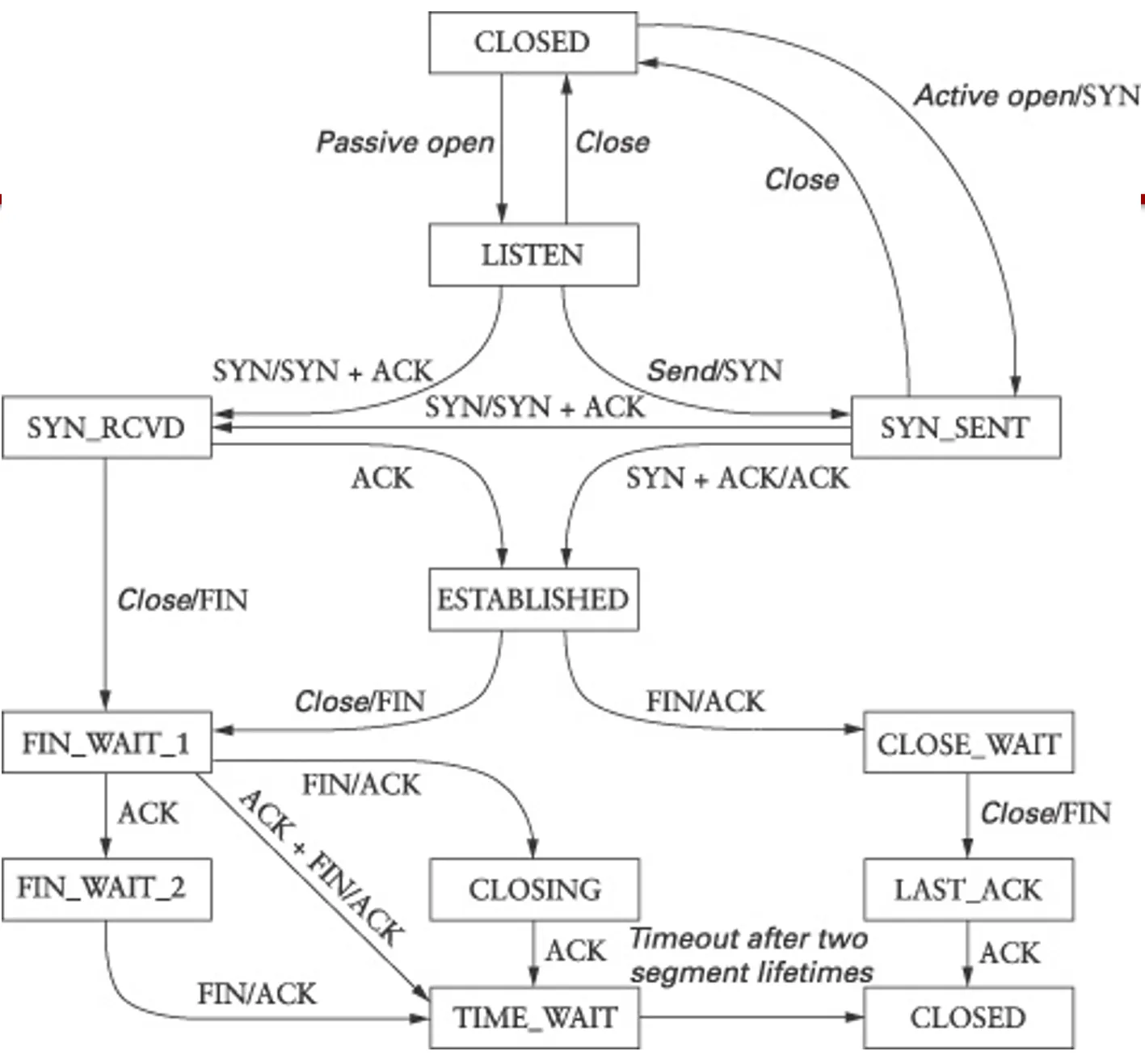
-
Transition: Opening a connection
-
Both sides create TCP endpoint (e.g., using socket calls)
-
TCP software on both sides record that connection is initially in CLOSED state
-
Server side issues passive open and waits in LISTEN state
-
Client issues active open, sends SYN segment, and moves to SYN SENT state
-
Server side receives SYN, sends SYN plus ACK, and moves to SYN RECVD state
-
Client receives SYN plus ACK, sends ACK, and moves to ESTABLISHED state
-
Server receives ACK and moves to ESTABLISHED state
-
Now both sides agree that connection is open
-
-
TCP 3-way handshake
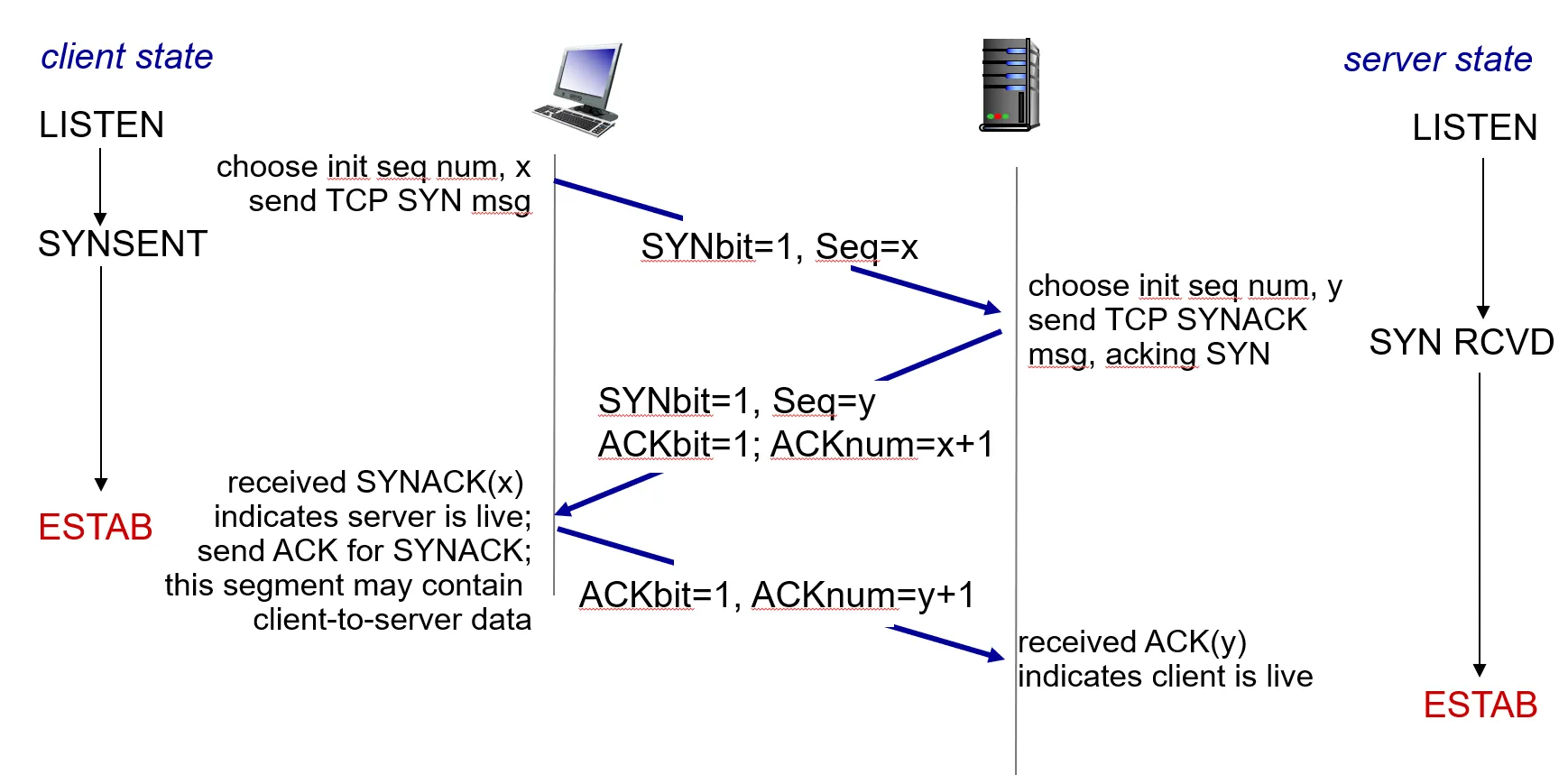
-
Maximum Segment Size
-
TCP endpoints use the MSS option to exchange the maximum segment that they are willing to receive
-
Improves efficiency
-
Is a function of the networks between the hosts
-
TCP tries to avoid sending segments that will have to be fragmented
-
Fragmentation decreases efficiency
-
Fragmentation decreases throughput
-
-
-
-
Normal sizes are network MTU for local connections and 576 for non-local
-
-
Adaptive Retransmission
-
The problem is knowing when to retransmit
-
TCP keeps estimate of round-trip time for each connection
-
Round-trip estimate computed from observing difference in times when segment transmitted, and time when ACK arrives
-
Timeout for retransmission is function of round trip estimate
-
-
TCP round trip time, timeout
-
Q: how to set TCP timeout value?
-
longer than RTT
- but RTT varies
-
too short: premature timeout, unnecessary retransmissions
-
too long: slow reaction to segment loss
-
-
Q: how to estimate RTT?
-
SampleRTT: measured time from segment transmission until ACK receipt
- ignore retransmissions
-
SampleRTT will vary, want estimated RTT “smoother”
- average several recent measurements, not just current SampleRTT
-
-
-
Principles of reliable data transfer
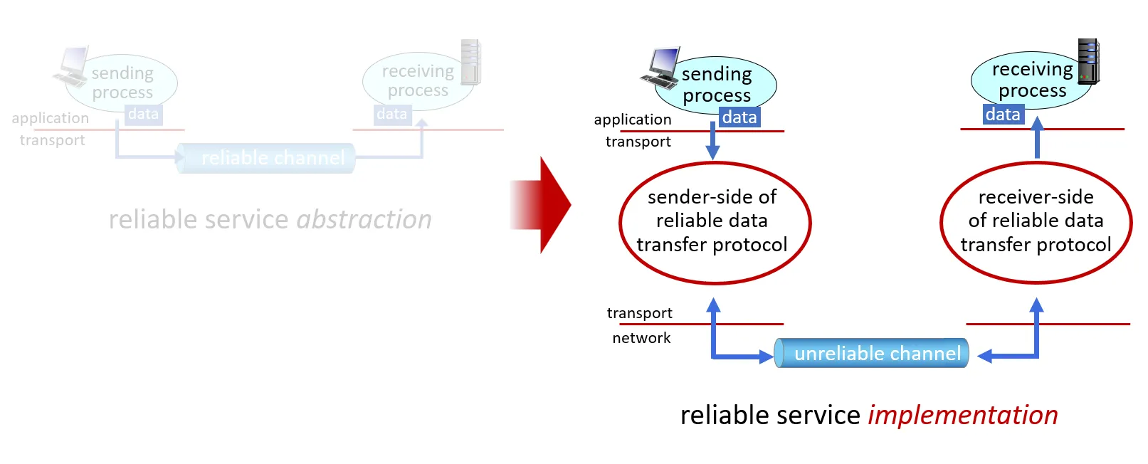
-
Complexity of reliable data transfer protocol will depend (strongly) on characteristics of unreliable channel (lose, corrupt, reorder data?)
-
Sender, receiver do not know the “state” of each other, e.g., was a message received?
- unless communicated via a message
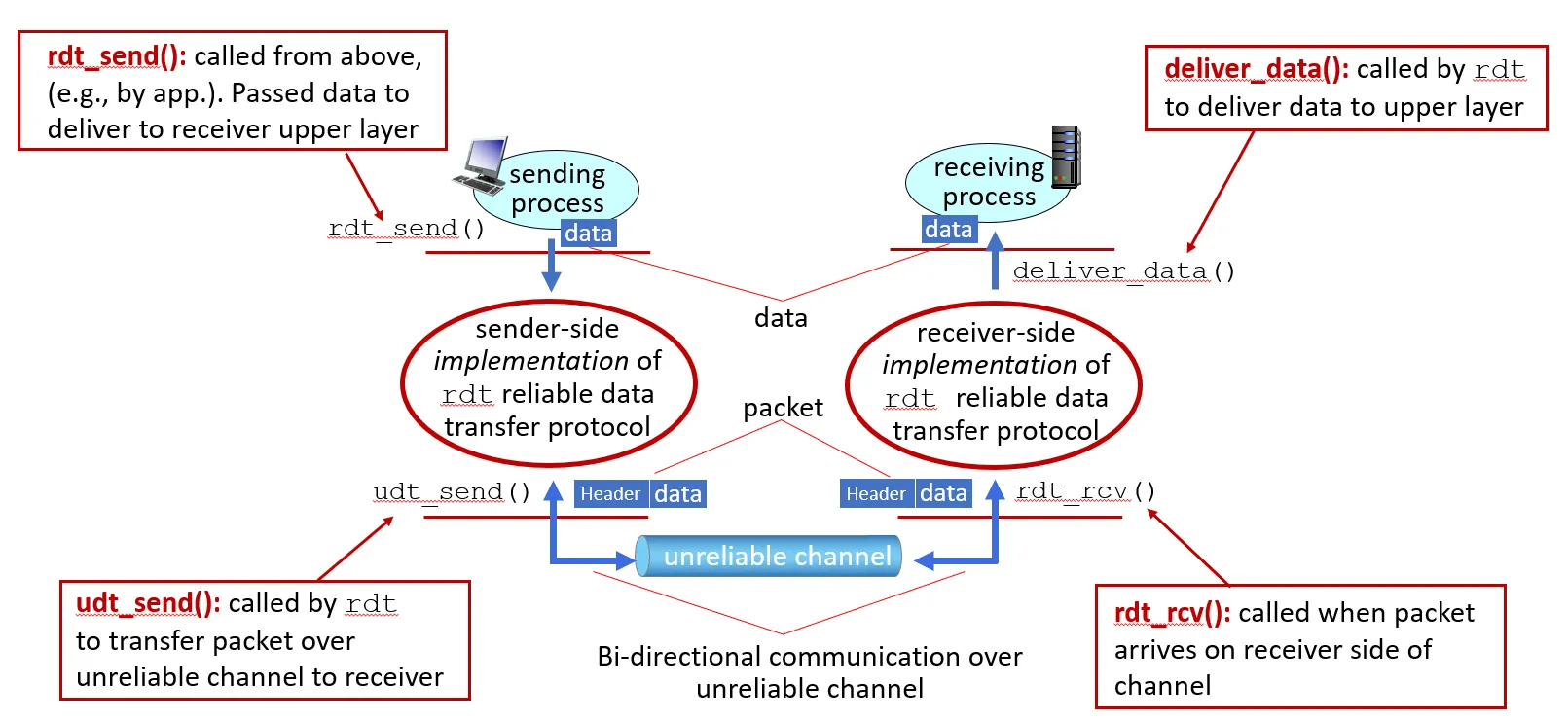
-
Getting started
-
We will:
-
incrementally develop sender, receiver sides of reliable data transfer protocol (rdt)
-
consider only unidirectional data transfer
-
but control info will flow on both directions!
-
-
use finite state machines (FSM) to specify sender, receiver
-
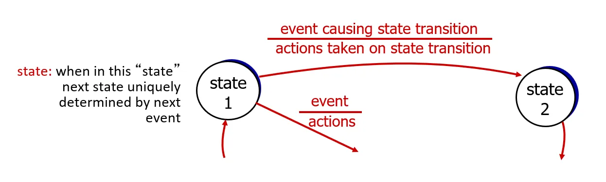
-
rdt1.0: reliable transfer over a reliable channel
-
underlying channel perfectly reliable
-
no bit errors
-
no loss of packets
-
-
separate FSMs for sender, receiver:
-
sender sends data into underlying channel
-
receiver reads data from underlying channel
-
-
-
rdt2.0: channel with bit errors
-
underlying channel may flip bits in packet
- checksum (e.g., Internet checksum) to detect bit errors
-
the question: how to recover from errors?
-
acknowledgements (ACKs): receiver explicitly tells sender that pkt received OK
-
negative acknowledgements (NAKs): receiver explicitly tells sender that pkt had errors
-
sender retransmits pkt on receipt of NAK
-
-
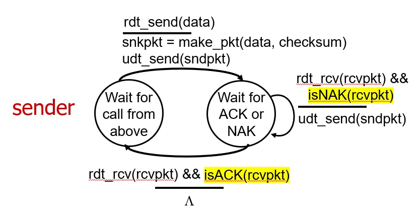
-
Note: “state” of receiver (did the receiver get my message correctly?) isn’t known to sender unless somehow communicated from receiver to sender
- that’s why we need a protocol!
-
rdt2.0 has a fatal flaw!
-
what happens if ACK/NAK corrupted?
-
sender doesn’t know what happened at receiver!
-
can’t just retransmit: possible duplicate
-
-
handling duplicates:
-
sender retransmits current pkt if ACK/NAK corrupted
-
sender adds sequence number to each pkt
-
receiver discards (doesn’t deliver up) duplicate pkt
-
-
-
rdt2.1: sender, handling garbled ACK/NAKs
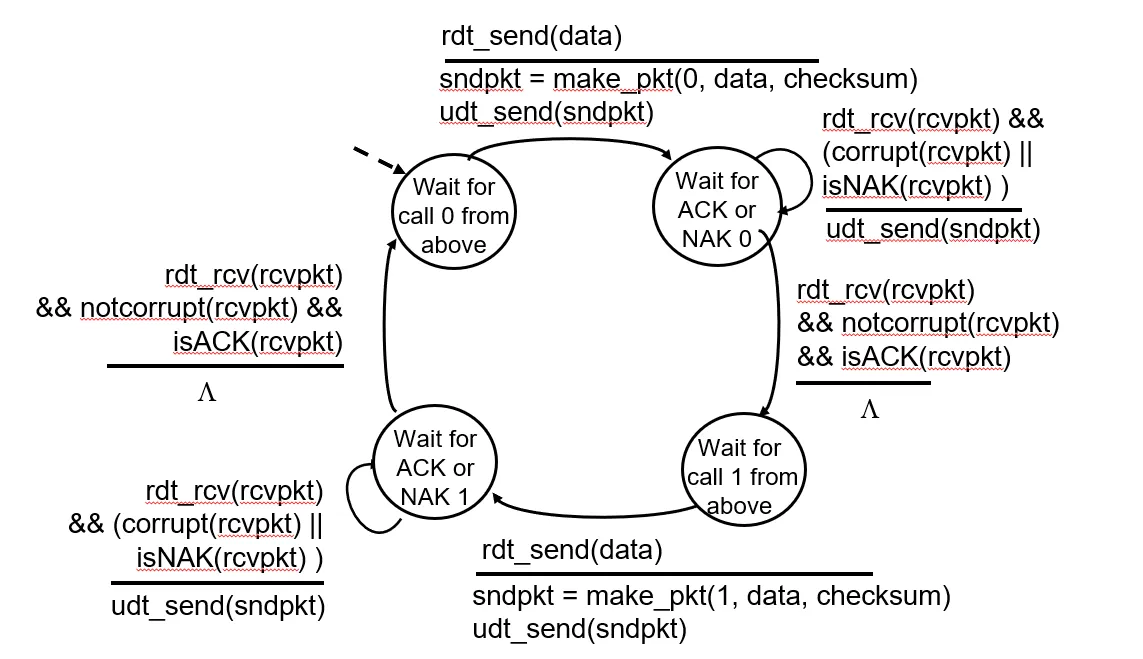
-
rdt3.0: channels with errors and loss
-
New channel assumption: underlying channel can also lose packets (data, ACKs)
- checksum, seq. #, ACKs, retransmissions will be of help … but not enough
-
Approach: sender waits “reasonable” amount of time for ACK
-
retransmits if no ACK received in this time
-
if pkt (or ACK) just delayed (not lost):
-
retransmission will be duplicate, but seq. #s already handles this
-
receiver must specify seq # of pkt being ACKed
-
-
requires countdown timer
-
-
-
Connection-Oriented Transport: TCP
-
Overview
-
point-to-point:
- one sender, one receiver
-
reliable, in-order byte steam:
- no “message boundaries” (continuous stream of bytes)
-
full duplex data:
-
bi-directional data flow in same connection
-
MSS: maximum segment size
-
-
cumulative ACKs
-
pipelining:
- TCP congestion and flow control set window size
-
connection-oriented:
- handshaking (exchange of control messages) initializes sender, receiver state before data exchange
-
flow controlled:
- sender will not overwhelm receiver
-
-
-
Application Layer
-
Our goals:
-
conceptual and implementation aspects of application-layer protocols
-
transport-layer service models
-
client-server paradigm
-
peer-to-peer paradigm
-
-
learn about protocols by examining popular application-layer protocols and infrastructure
-
HTTP
-
SMTP, IMAP
-
DNS (already covered prev.)
-
video streaming systems, CDNs
-
-
programming network applications
- socket API (covered in P2)
-
-
Network apps
-
social networking
-
Web
-
text messaging
-
e-mail
-
multi-user network games
-
streaming stored video (YouTube, Hulu, Netflix)
-
P2P file sharing
-
voice over IP (e.g., Skype)
-
real-time video conferencing (e.g., Zoom)
-
Internet search
-
remote login
-
…
-
-
Creating a network app
-
write programs that:
-
run on (different) end systems
-
communicate over network
-
e.g., web server software communicates with browser software
-
-
no need to write software for network-core devices
-
network-core devices do not run user applications
-
applications on end systems allows for rapid app development, propagation
-
-
-
Client-server paradigm
-
server:
-
always-on host
-
permanent IP address
-
often in data centers, for scaling
-
-
clients:
-
contact, communicate with server
-
may be intermittently connected
-
may have dynamic IP addresses
-
do not communicate directly with each other
-
-
examples: HTTP, IMAP, FTP
-
-
P2P architecture
-
no always-on server
-
arbitrary end systems directly communicate
-
peers request service from other peers, provide service in return to other peers
- self scalability — new peers bring new service capacity, as well as new service demands
-
peers are intermittently connected and change IP addresses
- complex management
-
example: P2P file sharing
-
-
Processes communicating
-
process: program running within a host
-
within same host, two processes communicate using inter-process communication (defined by OS)
-
processes in different hosts communicate by exchanging messages
-
note: applications with P2P architectures have client processes & server processes
-
client process: process that initiates communication
-
server process: process that waits to be contacted
-
-
-
Sockets
-
process sends/receives messages to/from its socket
-
socket analogous to door
-
sending process shoves message out door
-
sending process relies on transport infrastructure on other side of door to deliver message to socket at receiving process
-
two sockets involved: one on each side
-
-
-
Addressing processes
-
to receive messages, process must have identifier
-
host device has unique 32-bit IP address
-
Q: does IP address of host on which process runs suffice for identifying the process?
- A: no, many processes can be running on same host
-
identifier includes both IP address and port numbers associated with process on host.
-
example port numbers:
-
HTTP server: 80
-
mail server: 25
-
-
to send HTTP message to gaia.cs.umass.edu web server:
-
IP address: 128.119.245.12
-
port number: 80
-
-
more shortly…
-
-
An application-layer protocol defines:
-
types of messages exchanged,
- e.g., request, response
-
message syntax:
- what fields in messages & how fields are delineated
-
message semantics
- meaning of information in fields
-
rules for when and how processes send & respond to messages
-
open protocols:
-
defined in RFCs, everyone has access to protocol definition
-
allows for interoperability
- e.g., HTTP, SMTP
-
proprietary protocols:
- e.g., Skype, Zoom
-
-
-
What transport service does an app need
-
data integrity
-
some apps (e.g., file transfer, web transactions) require 100% reliable data transfer
-
other apps (e.g., audio) can tolerate some loss
-
-
timing
- some apps (e.g., Internet telephony, interactive games) require low delay to be “effective”
-
throughput
-
some apps (e.g., multimedia) require minimum amount of throughput to be “effective”
-
other apps (“elastic apps”) make use of whatever throughput they get
-
-
security
- encryption, data integrity, …
-
-
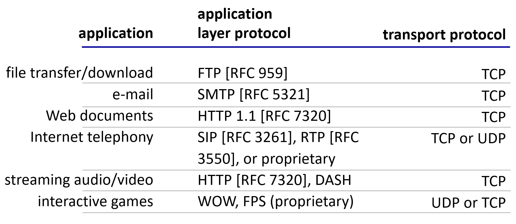
-
Web and HTTP
-
First, a quick review…
-
web page consists of objects, each of which can be stored on different Web servers
-
object can be HTML file, JPEG image, Java applet, audio file,…
-
web page consists of base HTML-file which includes several referenced objects, each addressable by a URL, e.g.,
-
-
-
HTTP overview
-
HTTP: hypertext transfer protocol
-
Web’s application-layer protocol
-
client/server model:
-
client: browser that requests, receives, (using HTTP protocol) and “displays” Web objects
-
server: Web server sends (using HTTP protocol) objects in response to requests
-
-
-
HTTP uses TCP:
-
client initiates TCP connection (creates socket) to server, port 80
-
server accepts TCP connection from client
-
HTTP messages (application-layer protocol messages) exchanged between browser (HTTP client) and Web server (HTTP server)
-
TCP connection closed
-
-
HTTP is “stateless”
- server maintains no information about past client requests
-
protocols that maintain “state” are complex!
-
past history (state) must be maintained
-
if server/client crashes, their views of “state” may be inconsistent, must be reconciled
-
-
Two types of HTTP connections
-
Non-persistent HTTP
-
TCP connection opened
-
at most one object sent over TCP connection
-
TCP connection closed
-
downloading multiple objects required multiple connections (more than one RTTs involved — see next three slides)
-
-
Persistent HTTP
-
TCP connection opened to a server
-
multiple objects can be sent over single TCP connection between client, and that server
-
TCP connection closed
-
-
-
Non-persistent HTTP: response time
-
RTT (definition): time for a small packet to travel from client to server and back
-
HTTP response time (per object):
-
one RTT to initiate TCP connection
-
one RTT for HTTP request and first few bytes of HTTP response to return
-
obect/file transmission time
-
-
-
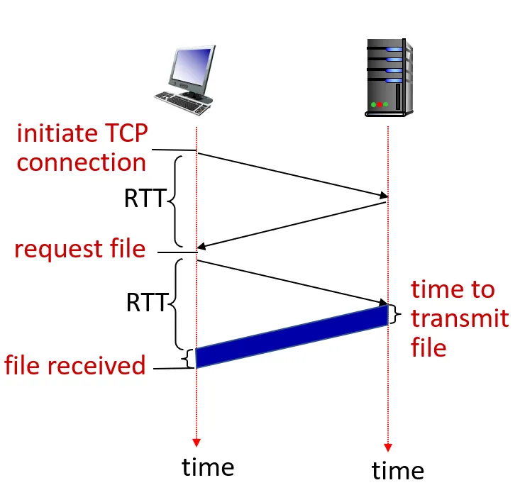
-
Non-persistent HTTP response time = 2RTT+ file transmission time
-
Persistent HTTP (HTTP 1.1)
-
Non-persistent HTTP issues:
-
requires 2 RTTs per object
-
OS overhead for each TCP connection
-
browsers often open multiple parallel TCP connections to fetch referenced objects in parallel
-
-
Persistent HTTP (HTTP1.1):
-
server leaves connection open after sending response
-
subsequent HTTP messages between same client/server sent over open connection
-
client sends requests as soon as it encounters a referenced object
-
as little as one RTT for all the referenced objects (cutting response time in half)
-
-
-
HTTP request message
-
two types of HTTP messages: request, response
-
HTTP request message:
- ASCII (human-readable format)
-
-
Other HTTP request messages
-
POST method:
-
web page often includes form input
-
user input sent from client to server in entity body of HTTP POST request message
-
-
HEAD method:
- requests headers (only) that would be returned if specified URL were requested with an HTTP GET method.
-
PUT method:
-
uploads new file (object) to server
-
completely replaces file that exists at specified URL with content in entity body of POST HTTP request message
-
-
GET method (for sending data to server):
- include user data in URL field of HTTP GET request message (following a ’?’):
-
-
HTTP response status codes
-
status code appears in 1st line in server-to-client response message.
-
some sample codes:
-
200 OK
- request succeeded, requested object later in this message
-
301 Moved Permanently
- requested object moved, new location specified later in this message (in Location: field)
-
400 Bad Request
- request msg not understood by server
-
404 Not Found
- requested document not found on this server
-
505 HTTP Version Not Supported
-
-
-
Maintaining user/server state: cookies
-
Recall: HTTP GET/response interaction is stateless
-
no notion of multi-step exchanges of HTTP messages to complete a Web “transaction”
-
no need for client/server to track “state” of multi-step exchange
-
all HTTP requests are independent of each other
-
no need for client/server to “recover” from a partially-completed-but-never-completely-completed transaction
-
-
Web sites and client browser use cookies to maintain some state between transactions
-
four components:
-
1) cookie header line of HTTP response message
-
2) cookie header line in next HTTP request message
-
3) cookie file kept on user’s host, managed by user’s browser
-
4) back-end database at Web site
-
-
Comments
-
What cookies can be used for:
-
authorization
-
shopping carts
-
recommendations
-
User session state (Web e-mail)
-
-
Challenge: How to keep state?
-
at protocol endpoints: maintain state at sender/receiver over multiple transactions
-
In messages: cookies in HTTP messages carry state
-
-
-
-
Video Streaming, Content Delivery Networks (CDNs)
-
stream video traffic: major consumer of Internet bandwidth
- Netflix, YouTube, Amazon Prime: 80% of residential ISP traffic (2020)
-
challenge: scale - how to reach ~1B users?
-
challenge: heterogeneity
- different users have different capabilities (e.g., wired versus mobile; bandwidth rich versus bandwidth poor)
-
solution: distributed, application-level infrastructure
-
Multimedia: video
-
video: sequence of images displayed at constant rate
- e.g., 24 images/sec
-
digital image: array of pixels
- each pixel represented by bits
-
coding: use redundancy within and between images to decrease # bits used to encode image
-
spatial (within image)
- instead of sending N values of same color (all purple), send only two values: color value (purple) and number of repeated values (N)
-
temporal (from one image to next)
- instead of sending complete frame at i+1, send only differences from frame i
-
-
CBR: (constant bit rate): video encoding rate fixed
-
VBR: (variable bit rate): video encoding rate changes as amount of spatial, temporal coding changes
-
examples:
-
MPEG 1 (CD-ROM) 1.5 Mbps
-
MPEG2 (DVD) 3-6 Mbps
-
MPEG4 (often used in Internet, 64Kbps — 12 Mbps)
-
-
-
Streaming stored video
-
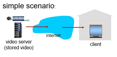
-
Main challenges:
-
server-to-client bandwidth will vary over time, with changing network congestion levels (in house, access network, network core, video server)
-
packet loss, delay due to congestion will delay playout, or result in poor video quality
-
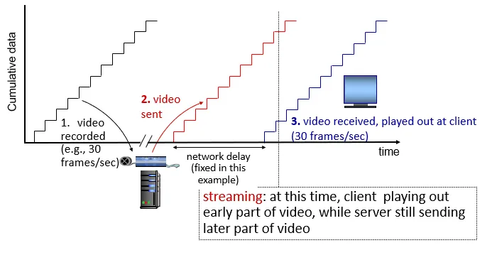
-
continuous playout constraint: during client video playout, playout timing must match original timing
- … but network delays are variable (jitter), so will need client-side buffer to match continuous playout constraint
-
other challenges:
-
client interactivity: pause, fast-forward, rewind, jump through video
-
video packets may be lost, retransmitted
-
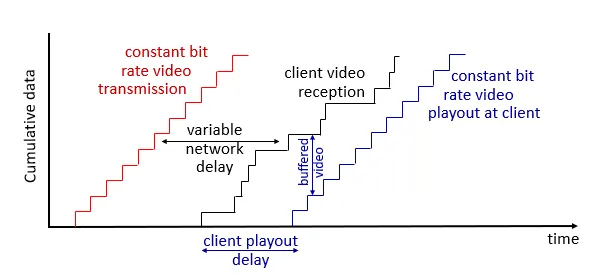
- client-side buffering and playout delay: compensate for network-added delay, delay jitter
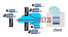
-
Streaming multimedia: DASH (Dynamic, Adaptive Streaming over HTTP)
-
server:
-
divides video file into multiple chunks
-
each chunk encoded at multiple different rates
-
different rate encodings stored in different files
-
files replicated in various CDN nodes
-
manifest file: provides URLs for different chunks
-
-
client:
-
periodically estimates server-to-client bandwidth
-
consulting manifest, requests one chunk at a time
-
chooses maximum coding rate sustainable given current bandwidth
-
can choose different coding rates at different points in time (depending on available bandwidth at time), and from different servers
-
-
“intelligence” at client: client determines
-
when to request chunk (so that buffer starvation, or overflow does not occur)
-
what encoding rate to request (higher quality when more bandwidth available)
-
where to request chunk (can request from URL server that is “close” to client or has high available bandwidth)
-
-
Streaming video = encoding + DASH + playout buffering
-
-
Content delivery networks (CDNs)
-
challenge: how to stream content (selected from millions of videos) to hundreds of thousands of simultaneous users?
-
option 1: single, large “mega-server”
-
single point of failure
-
point of network congestion
-
long (and possibly congested) path to distant clients
-
-
option 2: store/serve multiple copies of videos at multiple geographically distributed sites (CDN)
-
enter deep: push CDN servers deep into many access networks
-
close to users
-
Akamai: 240,000 servers deployed in > 120 countries (2015)
-
-
bring home: smaller number (10’s) of larger clusters in POPs near access nets
- used by Limelight
-
-
-
CDN: stores copies of content (e.g. MADMEN) at CDN nodes
-
subscriber requests content, service provider returns manifest
-
using manifest, client retrieves content at highest supportable rate
-
may choose different rate or copy if network path congested
-
Reading Notes:
- Layers
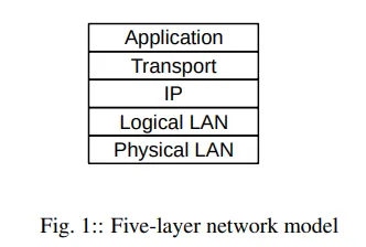
-
LANs, IP and TCP are often called layers
-
Local Area Networks (LANs) are the “physical” networks that provide the connection between machines within a home, school, or corporation
-
The Internet Protocol (IP) layer provides an abstraction for connecting multiple LANs to the Internet
-
TCP deals with transport and connections and sending user data
-
-
They constitute the Link layer, the Internet-work layer, and the Transport layer respectively
-
Together with the Application layer (the software I use), these form the four-layer model for networks
-
A layer ~= programming interface/library, it only communicates with the two layers directly above and below it
-
E.g. the application hands off a piece of data to the TCP library, which makes calls to the IP library, which calls the LAN layer for the actual delivery
-
-
The LAN layer is in charge of actual delivery of packets, using LAN-layer-supplied addresses. Consists of:
-
The physical layer: analog electrical, optical or radio signaling mechanisms involved
-
The logical layer: non-analog operations on packets
-
This separation would give us the five-layer model
-
-
Data Rate, Throughput, and Bandwidth
-
Data rate
- The rate at which bits are transmitted in any one network connection at the LAN layer
-
Throughput
-
Overall effective transmission rate
-
Disregarding transmission overhead, protocol inefficiencies, competing traffic, etc.
-
Generally measured at a higher network layer than the data rate
-
-
Bandwidth
- Can refer to either of those
-
Goodput
- Might also be called application-layer-throughput
-
Units
-
Commonly use kilobits per second (kbps) or megabits per second (Mbps)
-
In the context of data rates
-
1 kb = kilobit = 10^3 bits (not 2^10)
-
1 Mb = megabit = 10^6 bits
-
-
In the context of data volumes
-
1 kB = 1 kilobytes = 2^10 bytes
-
1 MB = 1 megabytes = 2^20 bytes
-
-
-
-
-
Packets
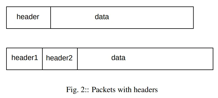
-
Modest-sized sequences of bytes
- Typically, packets are buffers built of 8-bit bytes
-
Transmitted as a unit through some shared set of links
-
Packets need to be prefixed with a header containing delivery information
-
In datagram forwarding, the header contains a destination address
-
In virtual-circuit forwarding, the headers contain an identifier for the connection
-
-
At the LAN layer, can think of packets of the imposition of a buffer (and addressing) structure on top of low-level serial lines
-
Additional layers then impose additional structure
-
Also called frames at the LAN layer and segments at the Transport layer
-
-
The maximum packet size supported by a given LAN is intrinsic to that LAN
-
Each layer adds its own header
- Ethernet header, IP headers, TCP headers, etc.
-
In datagram forwarding networks, internal nodes of the network called routers or switches will try to ensure that the packet is delivered to the requested destination on its header
-
Datagram Forwarding
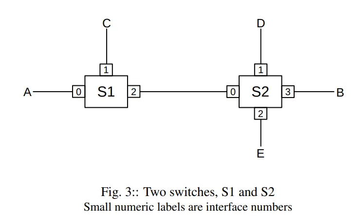
-
When delivering packets with the datagram-forwarding model, packet headers contain a destination address
- Intervening switches or routers look at this address and get the packet to its correct destination
-
Arriving packets query each switch’s forwarding table (<destination, next_hop> pairs), which gives a (presumed globally unique) next_hop information
-
next_hop is the immediate-neighbor address to/interface by which the packet should be forwarded to be one step closer to its final destination
-
The network of switches will deliver the packet, one hop at a time, to its destination if all goes well
-
-
The destination entries in the forwarding table do not have to correspond exactly with the packet destination addresses
-
Ethernet diagram forwarding is an exception
-
For IP routing, destination entries correspond to prefixes of IP addresses → huge space savings
-
Fundamental requirements: switch can do lookup operation
-
-
Stateless forwarding
-
No per-connection state in forwarding tables
-
Each packet is forwarded “in isolation”
-
The switches are not aware of higher-layer logical connections established between endpoints
-
Redundant paths are a result, provide robust service despite failures of intervening gateways and networks
-
-
IP routing in datagram forwarding can also be based on quality-of-service information
-
Different routing to the same destination for high-bandwidth bulk traffic and low-latency real-time traffic
-
In practice, most ISPs only route based on destination
-
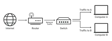
-
Switching devices at the LAN layer are called (Ethernet) switches
-
Destinations in forwarding tables are individual nodes
-
Operate based on MAC addresses, addresses that are used to identify devices within a LAN
-
-
Switching devices at the IP layer are called routers
-
Destinations in forwarding tables are entire networks (sets of nodes)
-
Operate based on IP addresses, addresses uniquely identify devices connected to a computer network
-
-
The alternative is virtual circuits
- Each router maintains state about each connection passing through it
-
Topology
-
If a network graph has no loops, there is no redundancy
-
Any broken link will partition the network into two isolated pieces
-
Redundancy is good
-
But we have to make decisions among multiple paths to a destination
-
-
Many LANs prefer acyclic tree networks with no redundancy
-
Less points of failure than IP routing
-
Simplify network management
-
-
IP has complex protocols in support of redundancy
-
Protocol to provide a metric to optimize for a path (cost, latency, etc.) → routing protocol
-
Protocol to use another path as a failover for the main path → redundancy/failover protocol
-
-
-
Routing Loops
-
A set of entries in the forwarding tables that cause packets to circulate endlessly
-
Can even occur in networks where the underlying link topology is loop-free → linear routing loop
-
All datagram-forwarding protocols need some way of detecting and avoiding routing loops
-
Ethernet
-
avoids nonlinear routing loops by disallowing loops in the underlying network topology
-
avoids linear routing loops by not having switches forward a packet back out the interface by which it arrived
-
-
IP
-
provides a one-byte “Time to Live” (TTL) field in the IP header
-
set by the sender and decremented by 1 at each router
-
packet is discard if its TTL = 0
-
limits the number of times a wayward packet can be forwarded, typically TTL = 64
-
-
-
Moral: successful datagram routing requires cooperation and a consistent view of the network
-
-
Congestion
-
Packets arriving faster than they can be sent out
-
A queue will be formed for a given outbound interface if there is congestion there
-
Queue full → packets will be dropped
-
The most common strategy is to drop any later arriving packets
-
-
In the Internet, most packet losses are due to congestion
- Other types of losses (e.g, packet corruption) are insignificant by comparison
-
May not be always bad
-
Bulk-traffic senders (not real-time) attempt to send as fast as possible, and congestion is just the network’s feedback that the maximum transmission rate has been reached
-
But is a problem in real-time networks
-
-
-
Packets Again
-
Packets are the key to supporting shared transmission lines
-
Support the multiplexing of multiple communications channels over a single cable
-
Packets → A shared medium
-
-
Maximum packet size
-
Unbounded packet sizes → prolonged network unavailability if someone downloaded a 1 Gigabit packet
-
If the packet is large and corrupted, the entire packet must be retransmitted
-
-
A router or switch (generally) reads in the entire packet before looking at the header → store-and-forward
-
Introduces a forwarding delay = the time to read the entire packet
-
Keep multiple packets en route at the same time → Overlap the processing of different packets to reduce forwarding delay → packet pipelining
-
-
Higher-end switches have cut-through switching to begin forwarding a packet before it has fully arrived
-
Total packet delay is the sum of:
-
Bandwidth delay, this is a per-link delay
-
Propagation delay due to the speed of light → 200 m/microsecond = 200 km/ms
-
Store-and-forward delay: sum of the bandwidth delays out of each router along the path
-
Queuing delay: waiting in line at busy routers, generally <10ms, often <1ms, can >1sec
- The only delay component amenable to reduction through careful engineering
-
-
-
LANs and Ethernet
-
A local-area network (LAN) is a system consisting of:
-
Physical links that are seriai lines
-
Common interfacing hardware connecting the hosts to the links
-
Protocols to make everything work together
-
-
The most common type of wired LAN is Ethernet
-
Cost low because high demand → economy of scale
-
Widely used in server rooms
-
Replaced by wireless LAN (Wi-Fi) in end-users
-
-
Early Ethernet were unswitched
-
Every host tap into one long primary cable wound throughout the building/floor
-
Two stations could transmit at the same time, making the data unintelligible → collision
-
Ethernet has features to minimize wasted bandwidth on collision
-
Every host receives every packet and it is up to their network card to determine if the arriving packet is addressed to the host → password sniffing
-
Every packet is received by every host
-
-
All Ethernets today are fully switched
-
Eliminates collisions
-
Packet is only delivered to its address
-
But introduces queuing issue
-
In practice, Ethernet switch queues rarely fill up
- Unlike IP router queues
-
-
Ethernet addresses are 6 bytes long =
-
Each Ethernet card (network interface) is assigned a unique address at its time of manufacture
-
Burned into the card’s ROM
-
Called the physical address/hardware address/MAC (Media Access Control) address
-
First 3 bytes = manufacturer
-
Last 3 bytes = serial number
-
Whereas, IP addresses are assigned by the local site
-
Benefits: Hosts known their addresses on startup, no manual configuration or server query needed
-
Continually monitor all arriving packets
- Grabs and forwards any packet that contains a destination address that matches its own physical address to the attached CPU via a CPU interrupt
-
-
Has a designated broadcast address
-
A host sending to the broadcast address has its packet received by every other host on the network
-
The recipient receives the broadcasted packet on one port and forwards it out every other port → propagates throughout the network
-
-
Traffic addressed to a particular host is called unicast
-
In switched Ethernet, the switches must have a forwarding-table record for each individual Ethernet address on the network → not scalable at large sizes
- Works well for networks up to 10,000 — 100,000 nodes
-
-
IP — Internet Protocol
-
Solves the scaling problem of Ethernet
-
Allows support for other types of LANs and P2P links
-
Should work to 10^10 nodes or more
-
Provides a global mechanism for addressing and routing → packets can be delivered from any host to any other host
-
IP addresses version 4 (IPv4) are 4 bytes (32 bits)
-
Part of the IP header
- Stays with the packet for its entire journey across the Internet
-
Follows the Ethernet header
- The Ethernet header only stays with the packet for 1 hop
-
(This applies for IPv6 as well) Divided into:
-
a network part (a prefix)
-
called the network number or network address or network prefix
-
Most forward decisions are made using only this
-
-
a host part (the remainder)
-
-
-
All hosts with the same network address (same network bits) are
-
on the same IP network
-
located together on the same LAN
-
assume that hosts on the same network address can reach each other directly via their LAN
-
-
Supports fragmentation — the division of large packets into multiple smaller ones
-
IP is a best effort system
-
No IP-layer acknowledgements or retransmissions
-
Send and hope the packet gets there
-
Represents connectionless networking
-
-
IP forwarding
-
IP routers use datagram forwarding to deliver packets
-
The destination values listed in the forwarding tables are network prefixes representing entire LANs != individual hosts
-
IP forwarding → delivery to the correct LAN
-
Procedure
-
IP header contains source address and destination address
-
Host determines whether destination is on the same LAN by comparing their network addresses (local)
-
If same, look up destination’s physical address, attach LAN header to packet, and send straight to destination via LAN
-
If not, host looks up router to use, it then forwards the packet to router using direct LAN delivery, the router queries its forwarding table to see the next_hop address
-
-
-
-
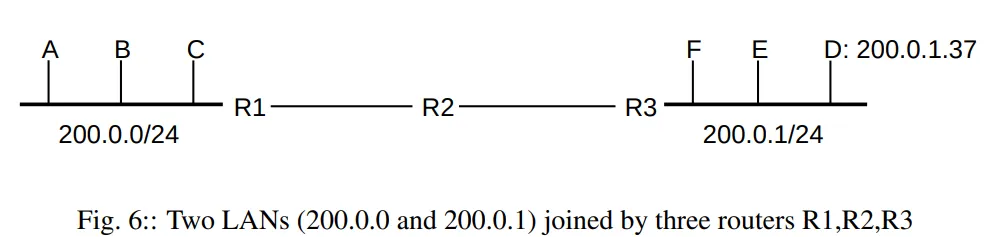
-
Network-host division in IP addresses
-
Routers only need to list network prefixes
-
IP scalability
-
Saves forwarding-table space
-
Faster lookup → saves time
-
Saves bandwidth and overhead
-
-
IP addresses are not human-friendly → domain name system (DNS)
-
Converts hierarchical text names to IP addresses
-
Software uses the same basic library calls to convert DNS names to actual addresses
-
Changing a website’s IP address while keeping the name
-
Have several DNS names resolve to the same IP address
-
Hierarchical & distributed → cs.luc.edu may requires queries to 4 different DNS servers
-
The DNS root zone
-
for edu
-
for luc.edu
-
for cs.luc.edu
-
-
Searching a hierarchy is cumbersome → DNS search results are cached locally
-
DNS hierarchy is not related to IP-address hierarchy
-
-
Transport
-
IP layer deficits
-
Best-effort service → packet delivery not guaranteed
-
Out-of-order delivery
-
Supports sending to a specific host, but host can have many applications running → no application-specific delivery
-
-
Creates a connection abstraction
-
TCP (Transmission Control Protocol)
-
The most popular mechanism in this layer
-
TCP extends IP with
-
reliability: lost packet re-transmission, ordered delivery, arrival acknowledgment
- timeout and retransmission occur when an acknowledgment packet isn’t received by the sender within a given time
-
connection-orientation: once a TCP connection is made, the application simply writes to the connection to send data
- Connections managed by the OS kernel
-
stream-orientation: TCP buffers and/or divide up data into appropriate-sized packets
-
port numbers: specify the receiving application, also identify the sending application
-
throughput management: TCP maximizes throughput while not contributing to network congestion
-
-
TCP endpoints have the form <host,port> → socket addresses
-
Servers listen for connections to sockets they have opened; the client is any endpoint that initiates a connection to a server
-
TCP uses slide sliding-window algorithm to keep multiple packets in-flight at any one time
-
Window size = # of packets simultaneously in transit
-
Slides over by one packet as each acknowledgement arrives
-
Minimizes store-and-forward and propagation delays
-
-
The real-time performance is not consistent
-
Lost packet will cause head-of-line blocking - host will stop sending until successful retransmission
-
Not suitable for sound and video applications → UDP
-
-
-
UDP (User Data Protocol)
-
Provides ports like TCP
-
Omits other TCP features
-
Faster start time for data transmission
-
No head-of-line blocking
-
The Real-Time Transport Protocol (RTP) builds on top of UDP and adds support for voice and video applications
-
-
Classic communication patterns
-
Bursty communications (ssh, telnet)
-
Bulk file transfers (downloading a web page)
-
Request/reply operations (database queries, DNS requests)
-
-
TCP handles all cases well
-
Most DNS traffic still uses UDP
-
Streaming video
-
TCP works here
-
Buffer video ahead for received-but-not-yet-viewed portion
-
Throughput dip → receiver has time to recover
-
Streaming-video services estimate available throughput and adapt to that by changing the video resolution
-
Sender pauses when receiver’s playback buffer is full and resumes when it drops below a certain threshold
-
-
Interactive (voice/video calls)
- UDP is used to avoid head-of-line blocking
-
Within the Transport layer, all connections have a client and a server
- The pattern is repeated in the Application layer
-
Content-distribution network (CDN)/Points of Presence (PoPs)/nodes/access points/edge servers
-
Specialized communication pattern for sites with an extremely large volume of content
-
Reduce the amount of long-distance traffic
-
Replicates site content at multiple data centers
-
User requests are routed to the nearest data center
-
Replicate static content of a web page
-
-
-
Firewalls
-
Buffer overflow
- Fills a memory buffer with network-supplied data without careful length checking
-
Firewall — a mechanism to block potentially risky connections
-
-
Useful Utilities
-
ping
- Determine if another machine is accessible
-
ifconfig, ipconfig, ip
- Find your own IP address
-
nslookup, dig, host
- DNS lookup
-
traceroute, mtr
- Lists the route from you to a remote host
-
route, netstat
- Display the host’s local IP forwarding table
-
netcat (nc)
- Create TCP or UDP connections and send lines of text back and forth
-
WireShark
- Packet capture and packet analysis
-